Safety tether for hand tools

a safety tether and hand tool technology, applied in the direction of vehicle safety belts, belt retractors, vehicle components, etc., can solve the problems of allowing unimpeded use of tools, and achieve the effects of preventing cable payout, shortening the distance below which the tool may fall, and being reliable and fast-acting

Inactive Publication Date: 2006-07-27
WOODHEAD IND INC
View PDF6 Cites 17 Cited by
  • Summary
  • Abstract
  • Description
  • Claims
  • Application Information

AI Technical Summary

Benefits of technology

[0006] The tension on the retractable cable is constant and such that the worker may readily maneuver the tool. The cable extends or shortens without overt action by the user and without having to overcome a substantial retraction force. The weight of the safety device is not substantial and does not add significantly to the weight of the tool. In short, the worker is not impeded substantially in the flexibility or utility of the tool, yet the tool users and surroundings are protected.
[0008] Inside the casing, a sliding lock plate is located beneath the ratchet plate of the retractable cable in the normal use (or upright) position, and has a configuration and teeth corresponding to the teeth of the ratchet plate, which are asymmetrical (preferably a sawtooth configuration) to prevent cable payout when the lock plate engages the hub in the inverted position of the casing. When the casing is in an upright position (that is, the tool clasp is located above the lock point at which the cable clasp is attached), the lock plate is disengaged from the ratchet plate of the retractable reel by gravity, thereby permitting unimpeded use of the tool.
[0010] The present invention provides a reliable, fast-acting, economical and light-weight safety tether or device for hand tools actuated by the fall itself, and preventing damage as well as injury.

Problems solved by technology

When the casing is in an upright position (that is, the tool clasp is located above the lock point at which the cable clasp is attached), the lock plate is disengaged from the ratchet plate of the retractable reel by gravity, thereby permitting unimpeded use of the tool.

Method used


Image

  • Safety tether for hand tools
  • Safety tether for hand tools
  • Safety tether for hand tools

Examples


Embodiment Construction

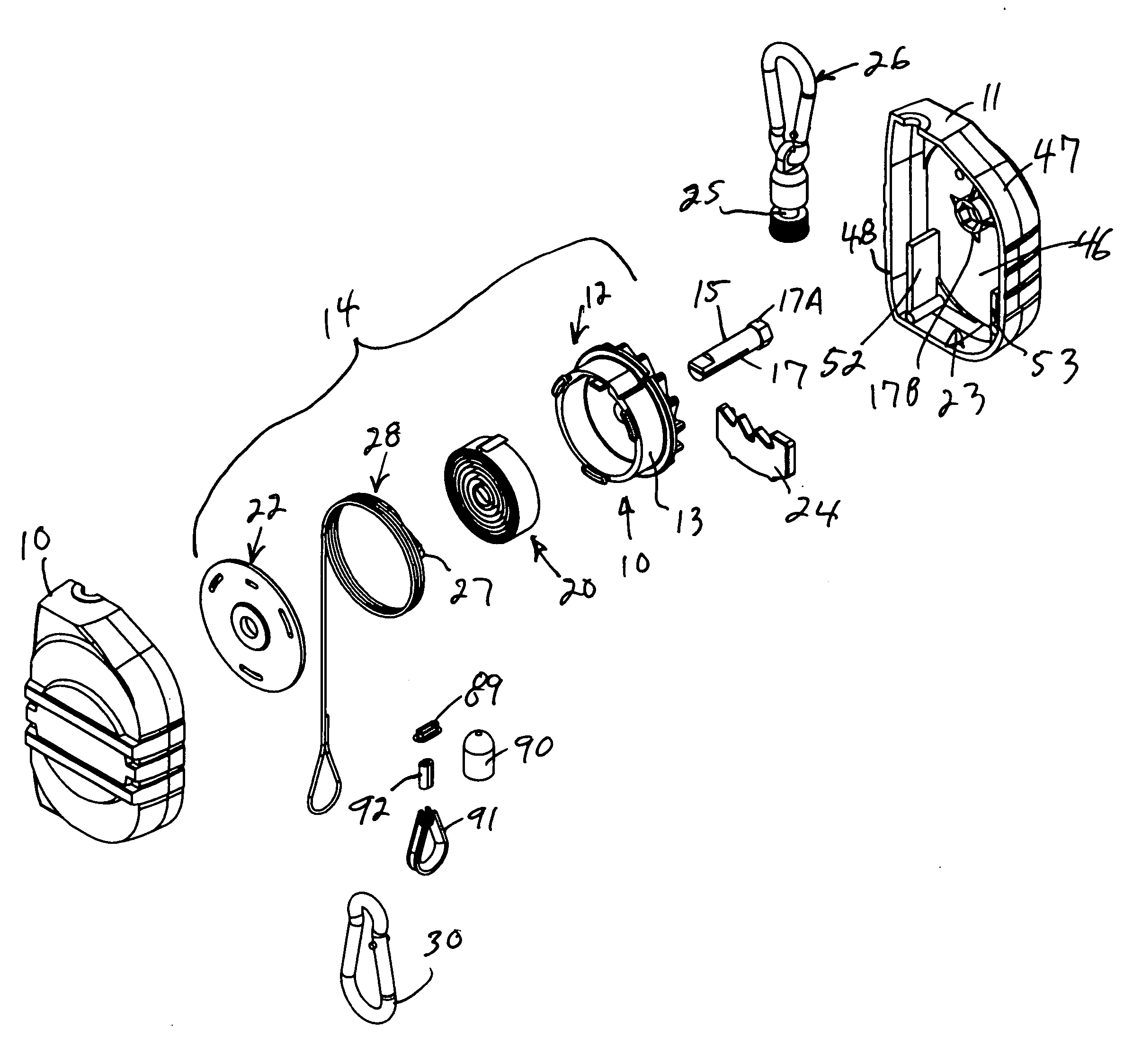
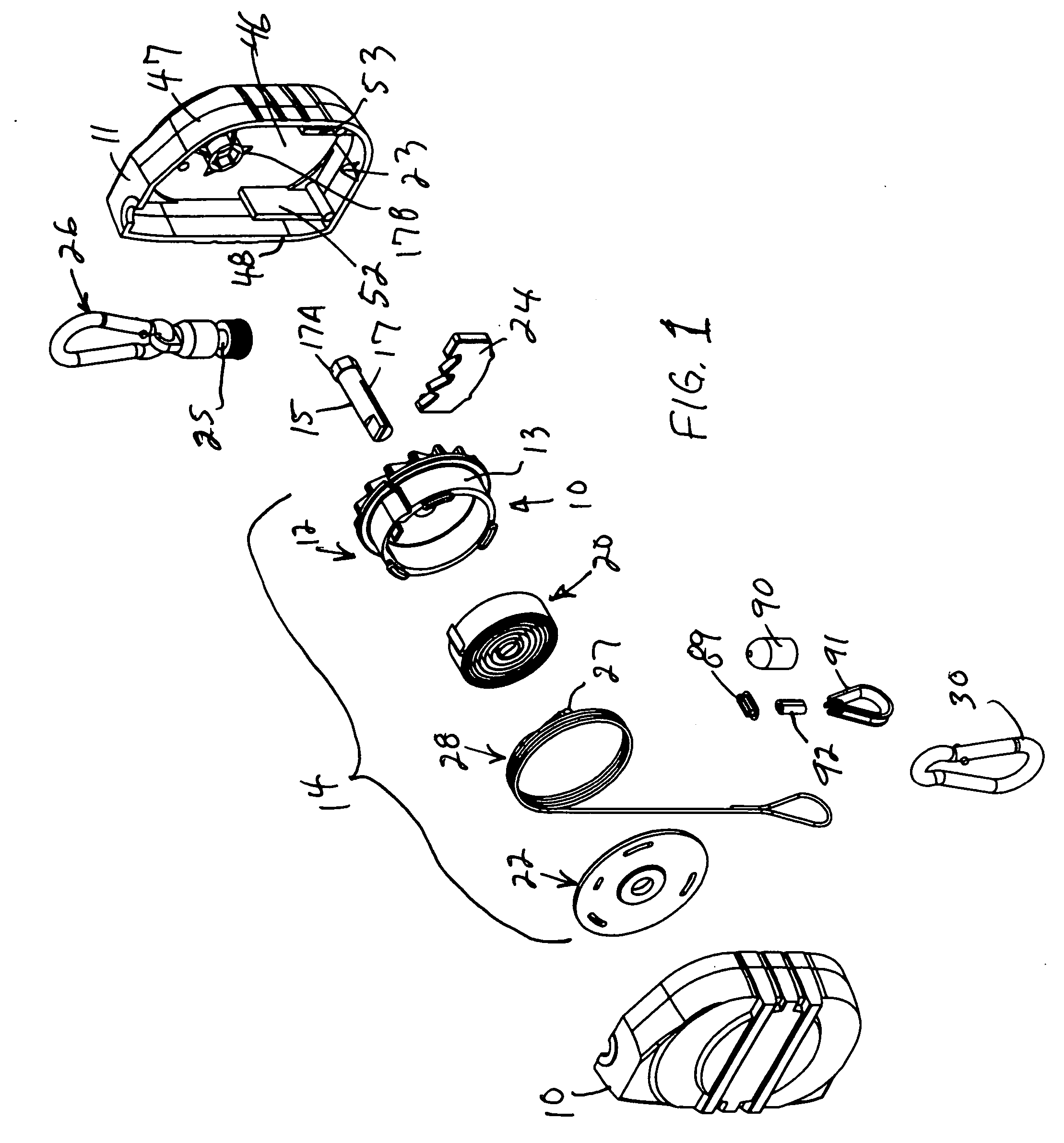
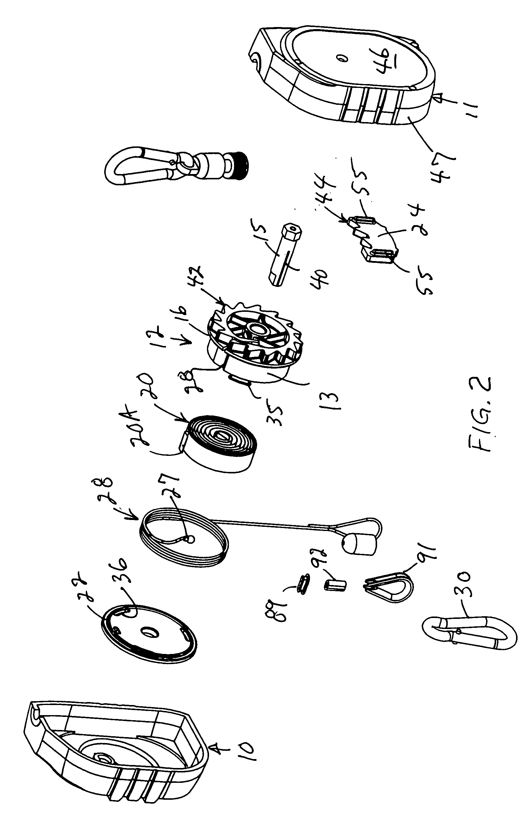
[0017] Referring to FIGS. 1 and 2, reference numerals 10 and 11 respectively designate first and second housing sections which cooperate to form a casing or outer housing. For convenience, and as will be better understood from the following description, the first housing section 10 is sometimes referred to as the left or spool housing; and the second housing section 11 is sometimes referred to as the right or ratchet housing. Housing sections 10, 11 cooperate to provide an outer housing 19 (FIG. 5) enclosing the cable reel and lock plate.

[0018] The two housing sections 10, 11 differ in some interior structure, but their peripheries are mirror images of one another, and they are designed with engaging edges to form a closed casing which encloses a retractable cable reel generally designated 14 and which is mounted on a shaft 15, the ends of which are mounted respectively to the spool housing section 10 and the ratchet housing section 11, as further described below.

[0019] Cable reel...


PUM


Abstract

A safety device for hand tools includes a casing having a first clasp secured to the casing for mounting to the tool. A second clasp is mounted to a retractable cable connected to a constant tension cable reel mounted within the casing: The cable is payed out of and retracted into the bottom of the housing in its normal use position, and the second clasp is attached to a fixed support or “lock point” located below the normal working height of the tool. In use, when the tool is held by a worker and the housing is upright, a lock plate is disengaged from a ratchet plate fixed to the retractable reel so the tool is freely moveable relative to the lock point and easily maneuvered. If the tool is dropped, the reel retracts the cable as the tool begins to fall. The device is inverted as it falls below the lock point. As the device turns over, the lock plate shifts under gravity, and the weight of the tool places the cable in tension and tries to counter-rotate the hub, thus causing the lock plate to rapidly engage the ratchet plate and lock the reel, preventing further cable pay out and securing the tool before it strikes the floor or ground.

Description

RELATED APPLICATION [0001] This application claims benefit of the priority filing of U.S. Provisional Application Ser. No. 60 / 647,497 filed on Jan. 27, 2005 for “SAFETY TETHER FOR HAND TOOLS”.FIELD OF THE INVENTION [0002] The present invention relates to a safety device for hand tools; and more particularly, it relates to a safety device for the type of hand tools typically used in the construction industry and other applications in which a worker may use the tool at levels above the shoulders of the user, and even at full arm's length above the user's head. If the tool were to fall from such a height and strike the floor, the impact could cause damage to the tool and / or any object struck by it. [0003] Hand tools of the type with which the present invention is concerned, include drills, electrically driven screw drivers, reciprocating chisels and the like. Some of these tools may weigh up to ten pounds; and they are used in a wide variety of work situations. In some cases, the worke...

Claims


Application Information

Patent Timeline
Patent Type & Authority Applications(United States)
IPC IPC(8): B65H75/48
CPCA62B1/08B65H75/4434
Inventor SZARKOWSKI, TADEUSZ C.ZITO, DONALD J.MACKIN, MICHAEL P.
Owner WOODHEAD IND INC
Why Eureka
Try Eureka