Identification sensor

a technology of identification sensor and detection sensor, which is applied in the field of identification sensor, can solve the problem that the completed product is erroneously determined to be a defective product, and achieve the effect of determining the authenticity, the accuracy and the like of an object, and excellent discriminating function

Inactive Publication Date: 2006-07-27
UNIVERSAL ENTERTAINMENT CORP +1
View PDF13 Cites 30 Cited by
  • Summary
  • Abstract
  • Description
  • Claims
  • Application Information

AI Technical Summary

Benefits of technology

[0005] The invention is accomplished to solve such problems. One of objects of the invention is to provide a discrimination sensor having an excellent discriminating function, which is enabled to determine the authenticity, the accuracy and the like of an object correctly or accurately without being affected by a displacement, deformation or the like of a surface structure of the object.

Problems solved by technology

Consequently, the conventional discrimination sensor has the following problems.
In the case of determining the accuracy of an integrated circuit, a completed product is erroneously determined to be a defective product.

Method used


Image

  • Identification sensor
  • Identification sensor
  • Identification sensor

Examples


first embodiment

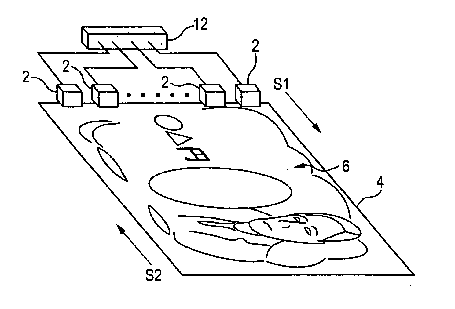
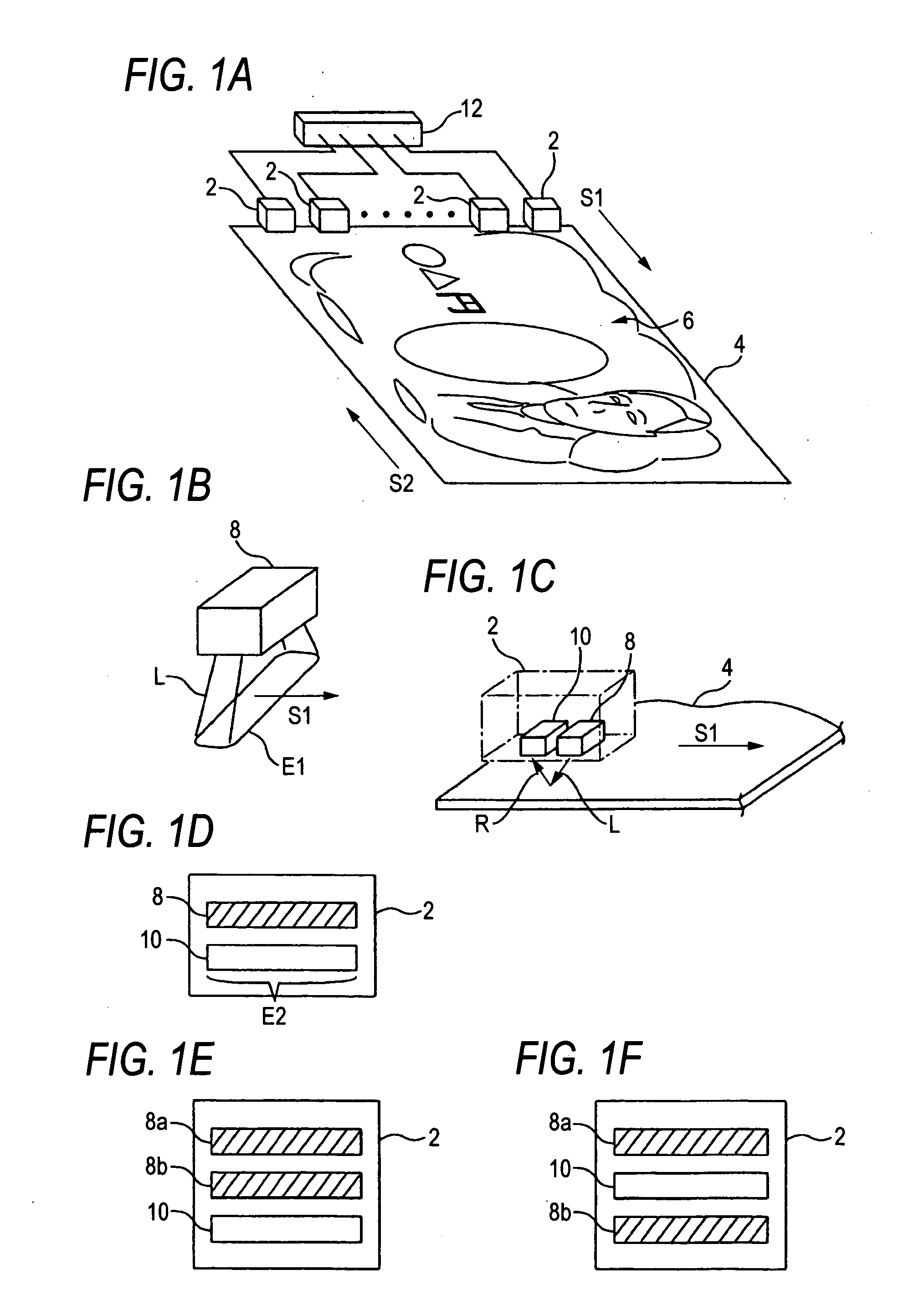
[0029]FIGS. 1B and 1C show the configuration of the discrimination sensor 2 according to the invention. Such a discrimination sensor 2 includes a light emitting device 8 adapted to emit sensing light L, the sensing area E1 corresponding to which extends in a direction perpendicular to the scanning direction S1 is wide, toward the surface of the object (or bill) 4, and also includes a light receiving device 10 adapted to receive light R generated on the surface structure 6 of the bill 4 when the sensing light L is emitted, and also adapted to assure a wide light receiving area E2 in a direction perpendicular to the scanning direction S1. The light emitting device 8 and the light receiving device 10 are formed integrally with each other in the discrimination sensor 2 (see FIG. 1D).

[0030] In the first embodiment, the light R generated on the surface structure 6 of the bill 4 is assumed to be reflection light reflected from the surface of the bill 4 when the sensing light L is emitted. ...

second embodiment

[0063] Further, although the light emitters of the second embodiment are respectively constituted by plural (two, in this embodiment) light emitting portions 8a and 8b each adapted to individually emit sensing light beams (that is, a near infrared light beam and a visible light beam) L of wavelength bands differing from each other. However, the light emitters according to this embodiment are not limited thereto. For example, as shown in FIGS. 5A and 5B, the light emitter may be constituted by a single light emitter enabled to individually emit sensing light beams (that is, a near infrared light beam and a visible light beam) L of wavelength bands differing from each other (with the predetermined timing alternately).

[0064] In this case, for example, a method of changing the oscillating wavelength of the light emitter 8′ by switching the value of the voltage applied to the light emitter 8′ can be employed as the method of causing the light emitter 8′ to individually emit plural sensin...


PUM

PropertyMeasurementUnit
wavelength bandaaaaaaaaaa

Abstract

A discrimination sensor includes a light emitting device individually emitting sensing light beams onto a surface of an object, such as a bill and having a sensing area that is wide in a direction perpendicular to a scanning direction; and a light detecting device assuring a light detecting area that is wide in a direction perpendicular to the scanning direction and detecting light coming from a surface structure of the bill when the sensing light is emitted. The light emitting device and the light detecting device are integrated with each other.

Description

TECHNICAL FIELD [0001] The present invention relates to a discrimination sensor having a function of discriminating an object at a high level. BACKGROUND ART [0002] Hitherto, as disclosed in Japanese Patent No. 2896288 (see paragraphs 0007-0009), there has been known a discrimination sensor configured to recognize a surface structure of an object (for example, a complex pattern applied to the surface of a bill, an integrated circuit or the like) and also adapted to determine the authenticity, the accuracy and the like of the object. Usually, the discrimination sensor of this kind is disposed at a position corresponding to a characteristic part of the surface structure (or the pattern), which best reflects the characteristic of the object. The object and the discrimination sensor are made to perform relative movement. This causes the discrimination sensor to scan along the characteristic part of the surface structure. Then, sensing data obtained during the scan (that is, data plotted...

Claims


Application Information

Patent Timeline
Patent Type & Authority Applications(United States)
IPC IPC(8): G01N21/88G06V30/144G07D7/12
CPCG07D7/121
Inventor FUJIMOTO, JUNYOSHIOKA, KAZUEI
Owner UNIVERSAL ENTERTAINMENT CORP
Why Eureka
Try Eureka