Card connector

a card connector and connector technology, applied in the direction of coupling device connection, instruments, conveying record carriers, etc., can solve the problems of system damage, system affecting signal discontinuity, and the credibility of the electric connection may be rattled in the connector, so as to ensure the credibility of the electric connection and reduce the height

Inactive Publication Date: 2006-07-27
JST MFG CO LTD
View PDF10 Cites 7 Cited by
  • Summary
  • Abstract
  • Description
  • Claims
  • Application Information

AI Technical Summary

Benefits of technology

[0026] A card connector according to the present invention can ensure credibility of electric contact between electrodes of an inserted card and contact elements against impact and vibration as well as can maintain the lowering of the height.

Problems solved by technology

Therefore, while being inserted into the connector, the SIM card may be rattled in the connector.
Such rattles generates intermittent discontinuity of power supply due to poor contact, which generates voltage drop, and has a considerable effect on a speech quality as a system.
In such a case, the credibility of the electric connection is damaged between the electrodes of the SIM card and the contact elements 35, and a system is affected by signal discontinuity, voltage drop, etc.

Method used


Image

  • Card connector
  • Card connector
  • Card connector

Examples


Embodiment Construction

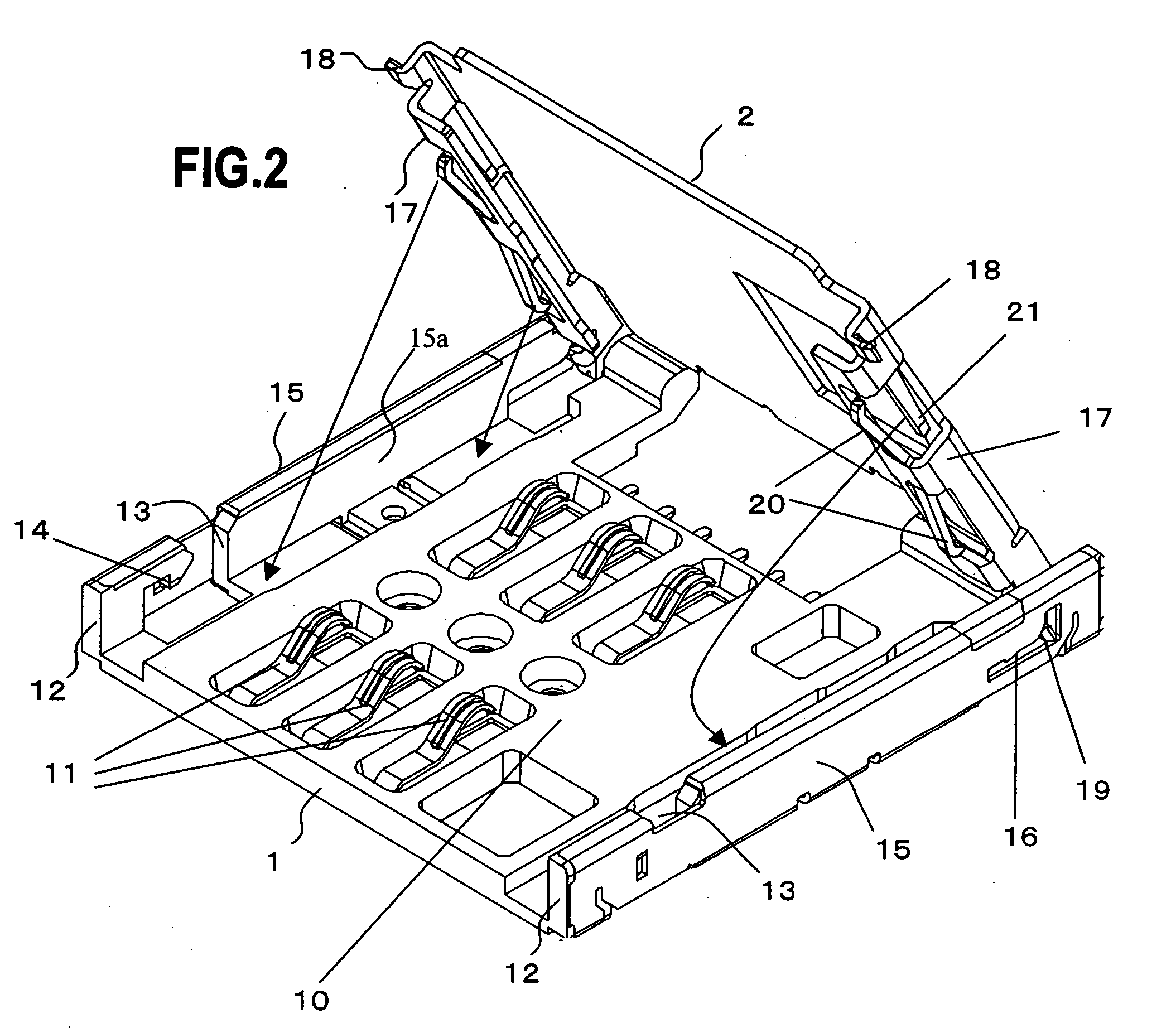
[0033] An exemplary embodiment of the present invention will now be described with reference to the accompanying drawings. The embodiment is for the purpose of describing the present invention and the technical scope of the present invention is not limited to the embodiment. In descriptions below, reference numerals are different from those used in FIG. 1.

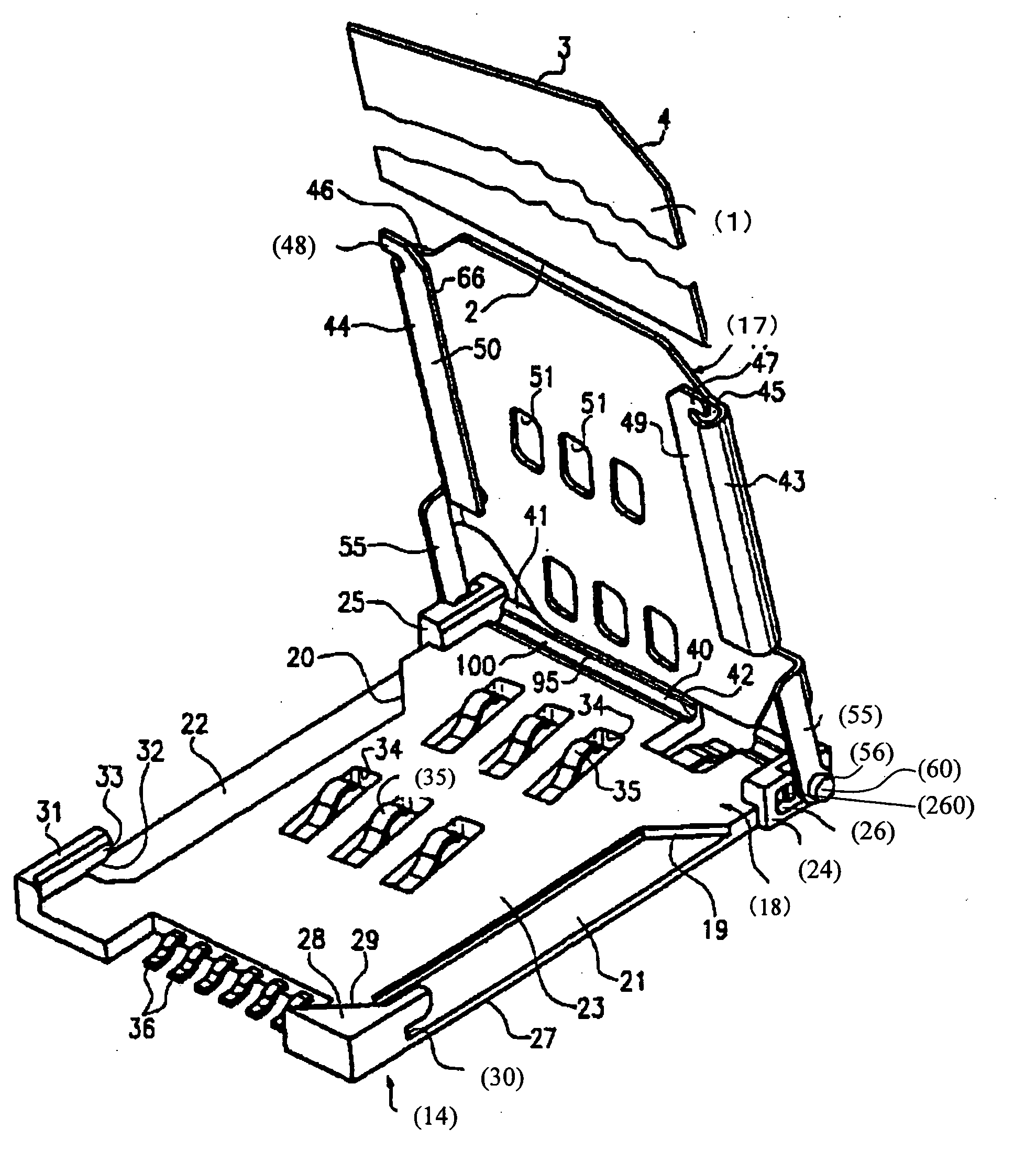
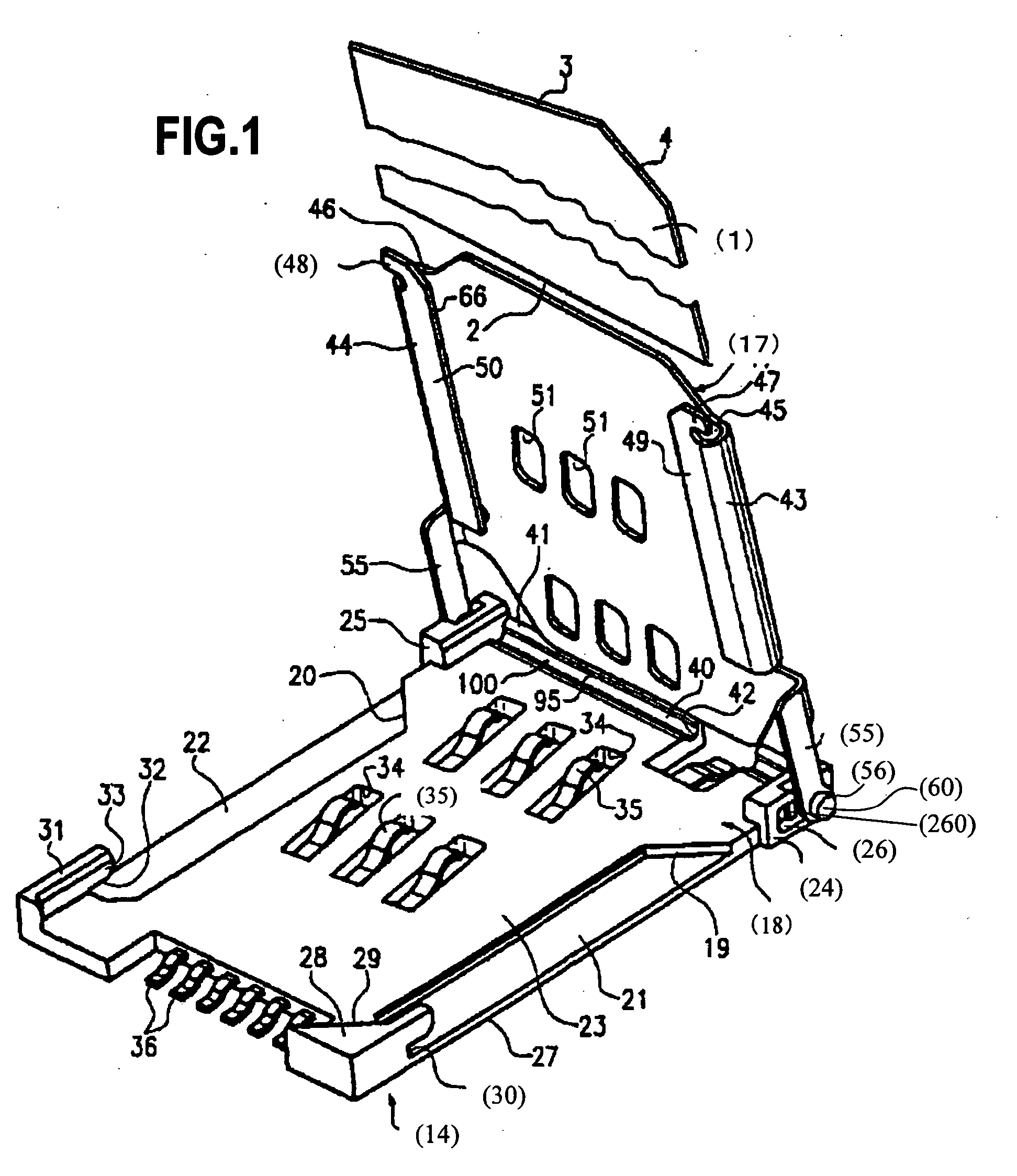
[0034]FIG. 2 is a perspective view of a configuration example of a card connector according to the present invention. The card connector is constituted by a body unit 1 and a tray (cover) 2 for inserting a card having a memory and a function unit, such as a SIM card.

[0035] The main body unit 1 is formed with resin mold. When doing this, the main body unit 1 is integrally formed such that a panel portion 10 has contact elements 11 with a spring property. A plurality of corresponding leads coupled to a plurality of the contact elements 11 is pulled out of the main body unit and, when the card connector is mounted on a device, the p...


PUM


Abstract

A card connector can ensure credibility of electric contact between electrodes of an inserted card and contact elements against impact and vibration as well as lowering of the height. The card connector has a main body unit having a panel portion including contact elements with a spring property, and having a rising portion on either side, the rising portion having at its front portion a notch portion followed by a hook portion, and having at its rear portion a generally L-shaped see-through hole; and a tray having a card holding portion for inserting a card, and having a front-portion tab and a rear-portion tab on either side, wherein when the tray is closed, the front-portion tab is in a position for engaging with the hook portion and the rear-portion tab is in a position at an end of a horizontal portion of the generally L-shaped see-through hole to regulate the movement of the tray in the back-and-forth direction.

Description

CROSS-REFERENCE TO RELATED APPLICATIONS [0001] This application is based upon and claims the benefit of priority from the prior Japanese Patent Application No. 2005-20368, filed on Jan. 27, 2005, the entire contents of which are incorporated herein by reference. BACKGROUND OF THE INVENTION [0002] 1. Field of the Invention [0003] The present invention relates to a card connector. More particularly, the present invention relates to a connector suitable for connecting a subscriber identity module (SIM). [0004] 2. Description of the Related Art [0005] If a manufacturer / distributor of a cellular phone (portable telephone) terminal is different from a telecommunications carrier, a card-type subscriber identity module (hereinafter, referred to as a SIM card) is used for authenticating a subscriber of the telecommunications carrier. [0006] For example, as described in Japanese Patent Application Laid-Open Publication No. 2004-228694, a connector is provided on a back side of a main body of ...

Claims


Application Information

Patent Timeline
Patent Type & Authority Applications(United States)
IPC IPC(8): H01R13/62
CPCG06K7/0021G06K13/0862H01R13/62H04B1/3816
Inventor UCHIDA, SHINJIMIYAO, TAICHIRO
Owner JST MFG CO LTD
Why Eureka
Try Eureka