Operating device and in-vehicle electronic device

Inactive Publication Date: 2006-07-27
DENSO CORP
View PDF14 Cites 6 Cited by
  • Summary
  • Abstract
  • Description
  • Claims
  • Application Information

AI Technical Summary

Benefits of technology

[0011] To achieve the above object, an operating device is provided with the following: An operating signal output unit is included for outputting an operating signal corresponding to an operation of an operating lever, which is used for controlling at least one of a turn-signal lamp and an illumination lamp of a vehicle. An information acquisition unit is included for acquiring information. A determination unit is included for determining based on the information acquired by the information acquisition unit whether or not the oper

Problems solved by technology

However, the in-vehicle electronic devices such as an audio device and a navigation device are not operated

Method used


Image

  • Operating device and in-vehicle electronic device
  • Operating device and in-vehicle electronic device
  • Operating device and in-vehicle electronic device

Examples


first embodiment

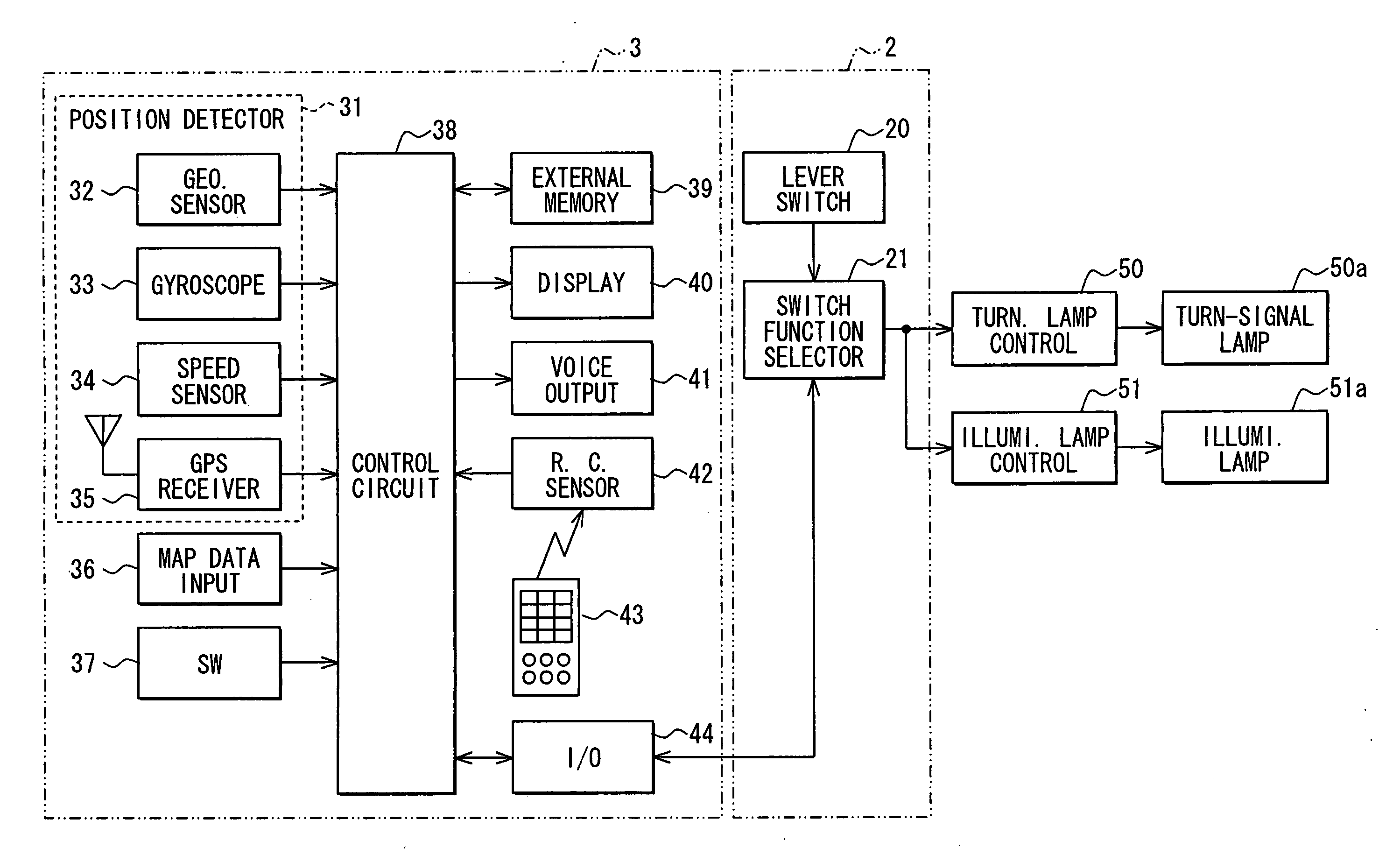
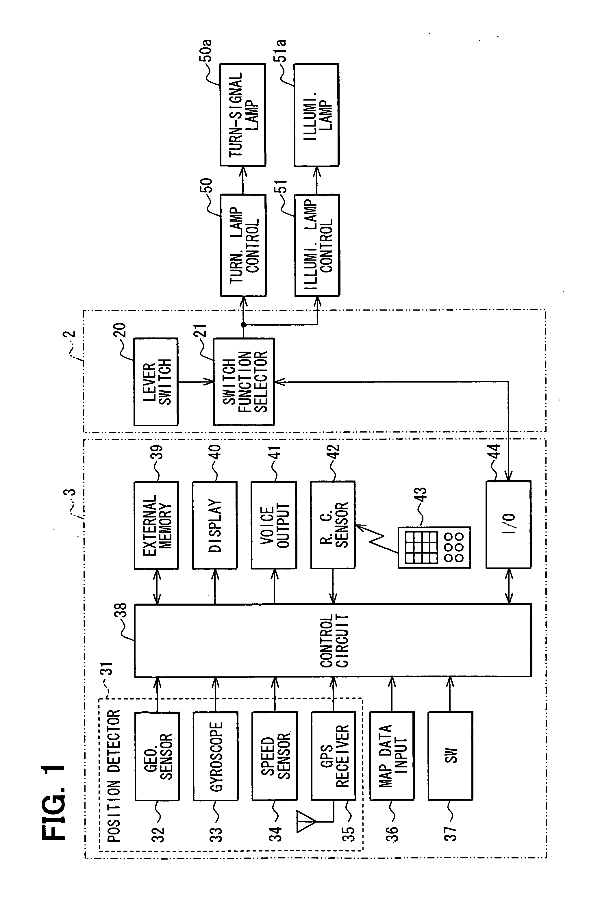
[0027]FIG. 1 shows an overall construction of an operating device and an in-vehicle electronic device according to a first embodiment of the present invention. In the present embodiment, a navigation device 3 will be described as the in-vehicle electronic device.

[0028] An operating device 2 has a lever switch 20 functioning as an operating signal output unit, and a switch function selector 21 functioning as a output selection unit. Further, the operating device 2 is connected respectively via cables with the navigation device 3, a turn-signal lamp controller 50, and an illumination lamp controller 51.

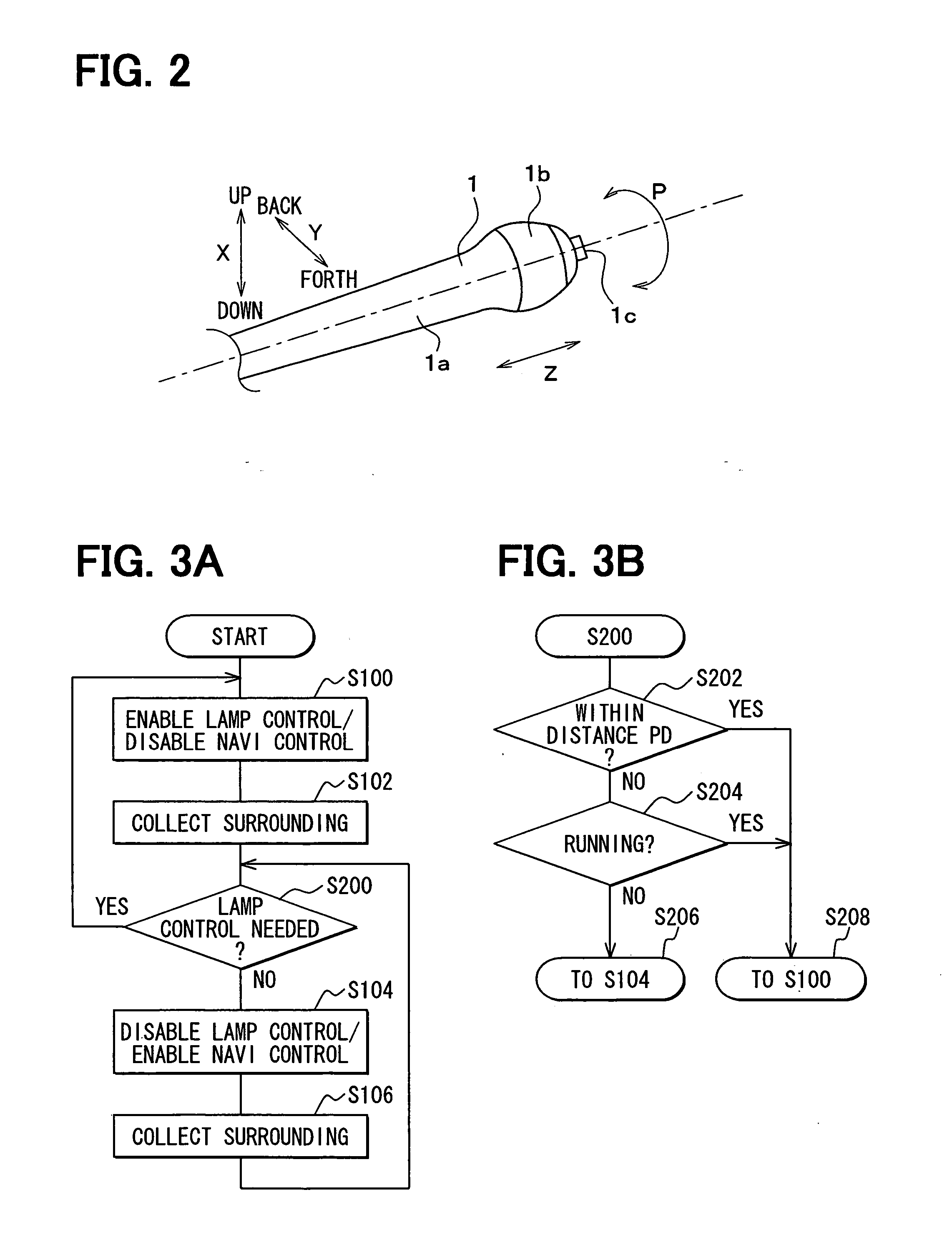
[0029] The lever switch 20 outputs an operating signal corresponding to an operation of each of (i) an operating lever 1 itself, (ii) a rotating knob 1b rotatably provided around an axis of a main lever 1a of the operating lever 1, and (iii) a determination button 1c provided at a distal end of the main lever 1a in an axial direction of the main lever 1a. A structure of the operating ...

second embodiment

[0091] Next, a second embodiment will be described. In the description, mainly the difference between the second embodiment and the first embodiment will be explained. FIG. 8 shows an overall construction of the operating device and the in-vehicle electronic device according to the second embodiment. Note that constituent elements corresponding to those of the above-described first embodiment have the same reference numerals and the explanations of the elements will be omitted. Hereinafter, only the difference from the first embodiment will be described. As shown in FIG. 8, the operating device 2 has the lever switch 20 and a switch function selector 23 functioning as an output selection unit.

[0092] The switch function selector 23 obtains illumination intensity around the vehicle from a solar radiation sensor 60 provided in the vehicle, and determines based on the information whether or not it is necessary to control lighting / light out of the illumination lamps 51a including the he...

third embodiment

[0106]FIGS. 10A and 10B show the structure of the operating lever 1 of the operating device 2 according to a third embodiment. FIG. 10A is a perspective view of the operating lever 1, and FIG. 10B is a schematic side view of a right-and-left-direction selection operating lever 1d viewed from an XB-direction in FIG. 10A.

[0107] The operating lever 1 of the operating device 2 according to the present embodiment, in comparison with the operating lever 1 in FIG. 2, is newly provided with a right-and-left-direction selection lever 1d as an attached operating unit. Further, a vertical-direction selection lever le in place of the determination button 1c shown in FIG. 2 is provided at the distal end portion of the operating lever 1.

[0108] As shown in FIG. 10B, the right-and-left-direction selection lever 1d is tilted in a right-and-left direction from a home position as a center in correspondence with the user's operation.

[0109] Further, the vertical-direction selection lever 1e is tilted...


PUM


Abstract

A switch function selector collects vehicle's positional information and road data of roads surrounding the vehicle from a navigation device, and thereby determines whether the turn-signal lamps need controlling. When affirmatively determining, the switch function selector outputs an operating signal from a lever switch to a turn-signal lamp controller. When negatively determining, the switch function selector outputs the operating signal to a navigation device.

Description

CROSS REFERENCE TO RELATED APPLICATIONS [0001] This application is based on and incorporates herein by reference Japanese Patent Application No. 2005-17055 filed on Jan. 25, 2005. FIELD OF THE INVENTION [0002] The present invention relates to an operating device that outputs an operating signal in correspondence with an operation of an operating lever to control turn-signal lamps and illumination lamps of a vehicle, and further relates to an in-vehicle electronic device operable based on the operating signal outputted from the operating device. BACKGROUND OF THE INVENTION [0003] In a vehicle such as an automobile, an operating lever to operate various car accessories, including illumination devices (e.g., headlights and position lamps) and turn-signal indicators, is provided on a steering column or the like. The operating lever is provided with various lever switches, and these lever switches detect an operation of the operating lever. The lever switches then output a detection sign...

Claims


Application Information

Patent Timeline
IPC IPC(8): G06F7/00
CPCB60Q1/1423B60Q1/346B60Q1/38B60Q2300/116B60Q2300/322B60Q2300/336B60Q1/381
Inventor MATSUMOTO, YUJIYOSHIDA, ICHIRO
Owner DENSO CORP
Why Eureka
Try Eureka