Video reception device, video transmission device, and video transmission system

a video reception device and video transmission technology, applied in the field of video transmission systems, can solve the problems of video quality degrading to an extreme degree, video data cannot be transmitted in real time, video data loss in the network and video halt,

Inactive Publication Date: 2006-07-27
PANASONIC CORP
View PDF23 Cites 29 Cited by
  • Summary
  • Abstract
  • Description
  • Claims
  • Application Information

AI Technical Summary

Benefits of technology

[0012] It is an object of the present invention to provide a video transmission system whereby uninterrupted video transmission can be achieved, even when there are l

Problems solved by technology

Therefore, if the video data bit rate is high compared with the transmission path bit rate, video data cannot be transmitted in real time, and not only does delay occur in video in a receiving apparatus, but video data is lost in the network and video halts (interruption occurs).
On the other hand, if the video data bit rate is lower than the transmission path bit rate, delay does not occur but video quality degrades to an extreme degree.
However, with conventional technology, video data bit rate co

Method used


Image

  • Video reception device, video transmission device, and video transmission system
  • Video reception device, video transmission device, and video transmission system
  • Video reception device, video transmission device, and video transmission system

Examples


embodiment 1

[0044] In this embodiment, a video transmission system that transmits a layered-coded video stream in an environment with large bit rate fluctuations, including wireless network, is described whereby uninterrupted video reception is made possible by lowering the base layer bit rate to the limit when large bit rate fluctuations are expected due to terminal movement and so forth.

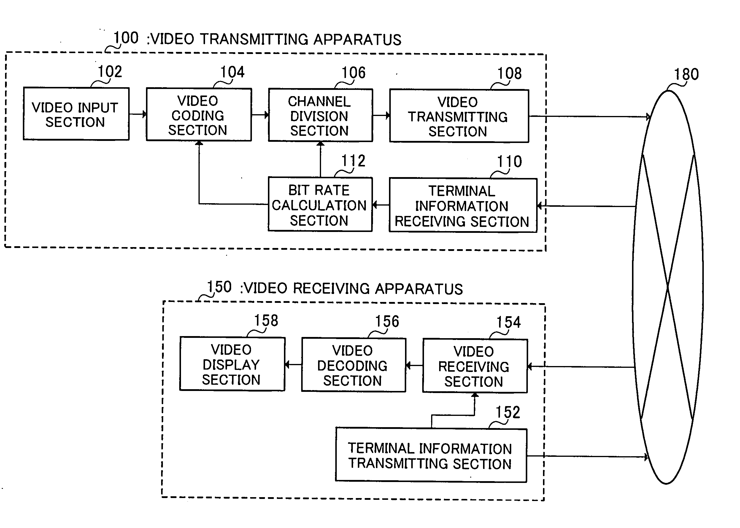
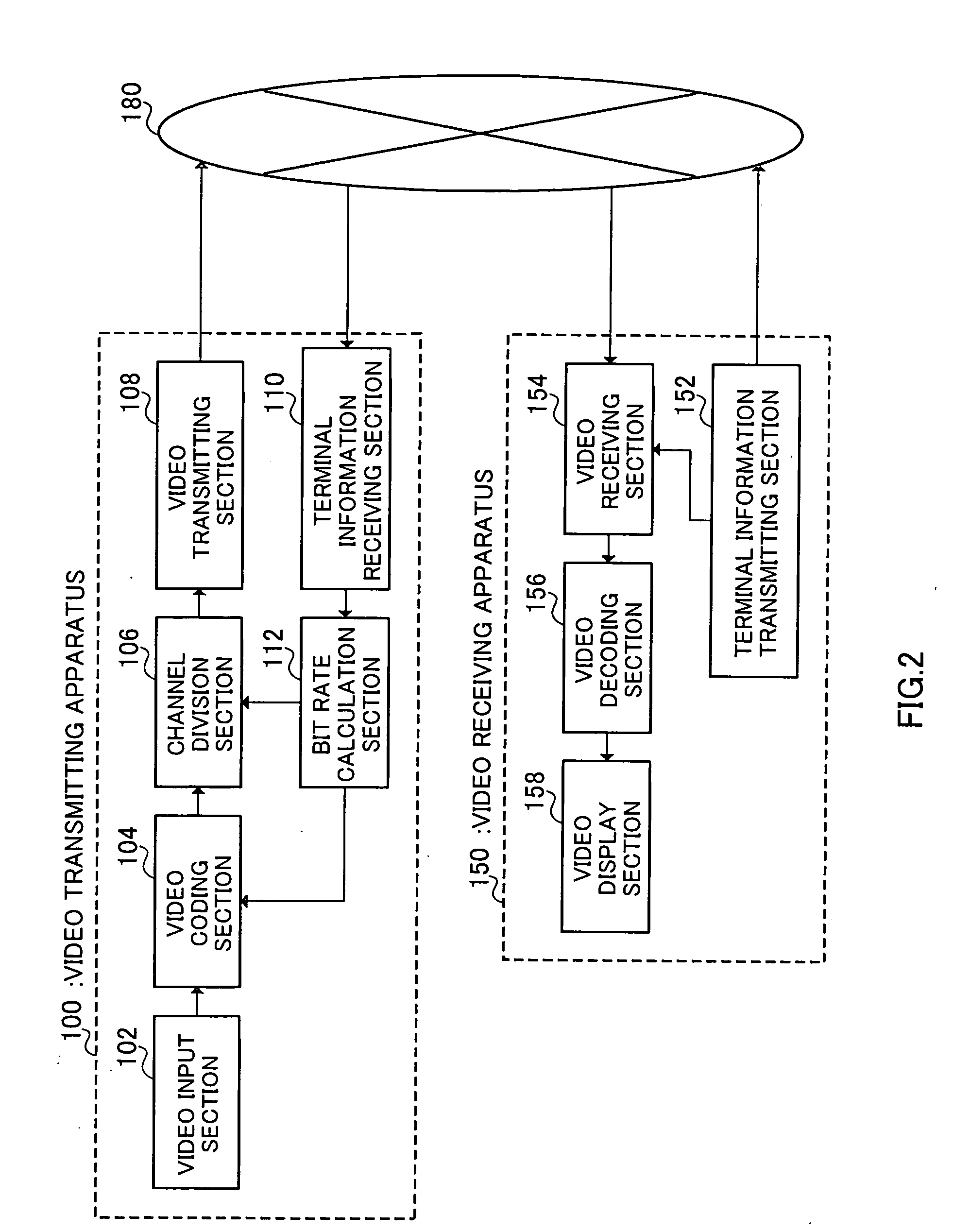
[0045]FIG. 2 is a drawing showing the configuration of a video transmission system according to Embodiment 1 of the present invention.

[0046] This video transmission system has a video transmitting apparatus (hereinafter also referred to as “transmitting terminal”) 100 that transmits video, a video receiving apparatus (hereinafter also referred to as “receiving terminal”) 150 that receives video, and a network 180 that relays video transmitted from video transmitting apparatus 100 to video receiving apparatus 150. That is to say, video transmitted from video transmitting apparatus 100 is transmitted to video ...

embodiment 2

[0098] In this embodiment, a video transmission system that transmits a layered-coded video stream in an environment with large bit rate fluctuations, including wireless network, is described whereby it is possible not only to achieve uninterrupted video reception, but also to prevent quality degradation due to a change of base layer bit rate, by lowering the base layer to the limit, and also raising the bit rate of the lowest enhancement layer (that is, the enhancement layer necessary for improving quality of the base layer), when large bit rate fluctuations are expected due to terminal movement and so forth.

[0099]FIG. 10 is a drawing showing the configuration of a video transmission system according to Embodiment 2 of the present invention. A video transmitting apparatus 200 in this video transmission system has a similar basic configuration to that of video transmitting apparatus 100 in the video transmission system shown in FIG. 2, and therefore identical configuration componen...

embodiment 3

[0112] In this embodiment, a video transmission system that transmits a layered-coded video stream in an environment with large bit rate fluctuations, including wireless network, is described whereby it is possible not only to achieve uninterrupted video reception, but also to improve received video quality to the greatest possible degree at the time of bit rate fluctuations, by lowering the base layer to the limit, and also finely dividing the bit rate of the lowest enhancement layer (that is, the enhancement layer necessary for improving quality of the base layer), when large bit rate fluctuations are expected due to terminal movement and so forth.

[0113]FIG. 13 is a drawing showing the configuration of a video transmission system according to Embodiment 3 of the present invention. A video transmitting apparatus 300 in this video transmission system has a similar basic configuration to that of video transmitting apparatus 100 in the video transmission system shown in FIG. 2, and t...


PUM


Abstract

A video transmission system that achieves uninterrupted video transmission, even when there are large bit rate fluctuation due to receiving terminal movement and so forth, in a network such as a wireless network in which transmission bit rate fluctuations occur. In this system, when a video receiving apparatus (receiving terminal) 150 is moving, a video transmitting apparatus (transmitting terminal) 100 lowers the base layer bit rate of layered-coded data to the limit. When the base layer bit rate is lowered in this way, the bit rate of the lowest enhancement layer is raised and effects on the received image quality of other terminals due to lowering of the base layer are suppressed, or the lowest enhancement layer is divided finely and the adjustability to a bit rate under bit rate fluctuations is improved.

Description

TECHNICAL FIELD [0001] The present invention relates to a video transmission system that transmits video via a network. BACKGROUND ART [0002] Video data transmitted by a conventional video transmission system is normally compression-coded into a fixed bit rate or below by means of a method such as H.261 or MPEG (Moving Picture Experts Group) so that it can be transmitted with a fixed transmission bit rate, and once video data has been coded the video quality cannot be changed even if the transmission bit rate changes. Here, a bit rate indicates a transmission bit rate. [0003] However, with the diversification of networks in recent years, transmission path bit rate width fluctuations have become large, and video data has become necessary that enables video transmission at quality commensurate with a plurality of bit rates. In response to this need, layered coding methods have been standardized that have a layered structure and can handle a plurality of bit rates. Among such layered c...

Claims


Application Information

Patent Timeline
IPC IPC(8): H04N7/173
CPCH04N7/167H04N21/23476H04N21/4621H04N21/6373H04N21/6377H04N21/658
Inventor HONDA, YOSHIMASAUENOYAMA, TSUTOMU
Owner PANASONIC CORP
Why Eureka
Try Eureka