Female terminal fitting

a terminal fitting and female technology, applied in the direction of coupling contact members, coupling device connections, coupling/insulating coupling contact members, etc., can solve the problems of reducing the resistance of the operator and affecting the fit of the two housings. , to achieve the effect of reducing the resistance to the force of inserting the tab into the body, facilitating the insertion into the body, and reducing the resistan

Inactive Publication Date: 2006-08-03
SUMITOMO WIRING SYST LTD
View PDF2 Cites 28 Cited by
  • Summary
  • Abstract
  • Description
  • Claims
  • Application Information

AI Technical Summary

Benefits of technology

[0009] The contact of the contact projection preferably is at a side of the support with respect to the apex in the longitudinal direction. Thus, the tab starts to engage the contact after the tab passes the apex and the tab increases the gap between the elastic contact piece and the opposed wall. Accordingly, a force for inserting the tab into the body will not increase rapidly after the tab engages the contact and hence the tab is inserted into the body more easily. Further the contact of the contact projection is to the side of the support with respect to the apex of the female terminal fitting. Therefore it is possible to secure a stable contact pressure between the contact and the tab after the tab is inserted into the body.
[0010] The contact projection preferably is sloped to incline from the contact towards the insertion opening. The slope starts at a bulge start point that aligns with the apex in the axial direction or is to the side of the support with respect to the apex in the axial direction. Therefore the gap between the contact and the opposed wall becomes large when the tab is inserted into the body, and resistance to the force for inserting the tab into the body is reduced significantly. Further it is possible to secure a stable contact pressure after the tab is inserted into the body part.
[0011] The contact of the contact projection preferably is aligned with the apex in a direction orthogonal to the axial direction or is to the side of the support with respect to the apex in the direction orthogonal to the axial direction. Therefore, resistance to the force for inserting the tab into the body is reduced significantly and secure a stable contact pressure is achieved after the tab is inserted into the body.
[0012] The front end of the tab preferably is tapered and the elastic contact piece contacts the tapered surface when the elastic contact piece starts to contact the tab. Therefore the elastic contact piece starts to perform a smooth flexing operation.
[0013] The operation of the sliding contact between the tab and the elastic contact piece starts from the state in which the contact projection contacts the tapered surface. Therefore the elastic contact piece performs a smooth flexing operation.

Problems solved by technology

Thus, the force of inserting the tab 2 into the gap is liable to increase rapidly, and an operator may have trouble fitting two housings together.

Method used


Image

  • Female terminal fitting
  • Female terminal fitting
  • Female terminal fitting

Examples


Embodiment Construction

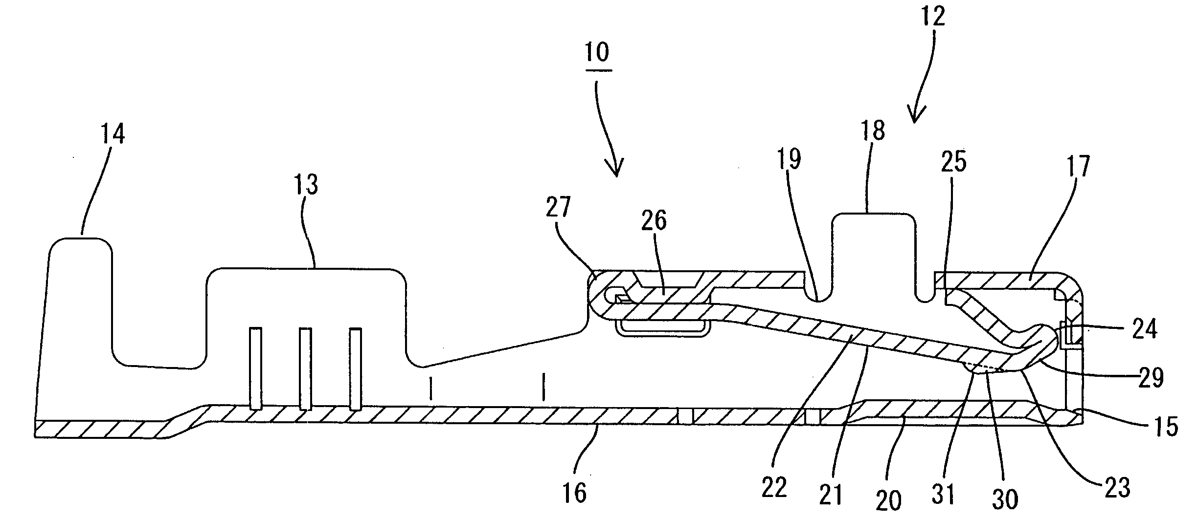
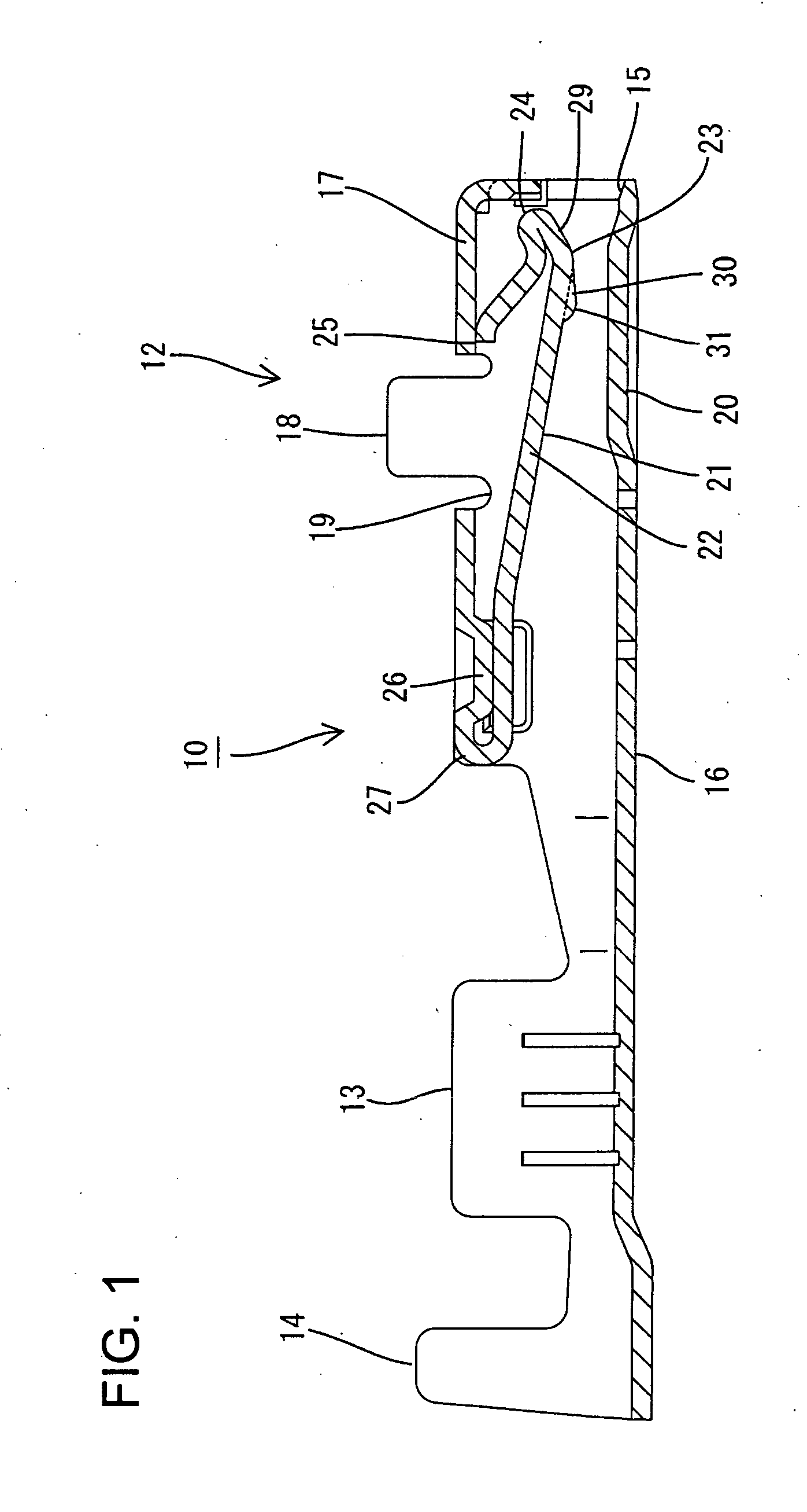
[0023] A female terminal fitting according to the invention is identified by the numeral 10 in FIGS. 1 through 8 and is formed by bending a conductive metal plate. The female terminal fitting 10 is long and narrow in a longitudinal or axial direction.

[0024] A body 12 is formed at the front end of the female terminal fitting 10 and is configured for receiving a tab 11 of a mating male terminal fitting. A wire barrel 13 is disposed rearward from the body part 12 and is configured to be caulked to an end of a core wire of a covered electric wire (not shown). An insulation barrel 14 is rearward from the wire barrel 13 and is configured to be caulked to an insulated part of the wire. The wire barrel 13 and the insulation barrel 14 have a pair of crimping pieces 13A and a pair of crimping pieces 14A with respect to the axis of the female terminal fitting 10.

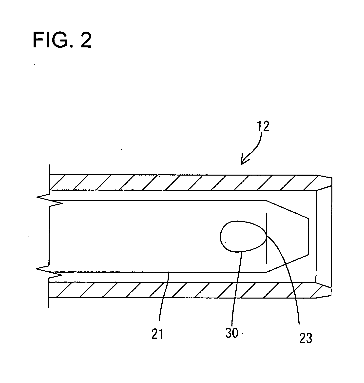
[0025] The body 12 is formed by bending the material widthwise in the shape of a square tube or pillar. An insertion opening 15 is ...


PUM


Abstract

A female terminal fitting has a rectangular tubular body (12) with opposed first and second walls (16, 17) and an insertion opening (15) for receiving a tab (11). An elastic contact piece (21) is inside the body (12) and extends obliquely from a support (27) on the second wall (17) of the body (12) towards both the first wall (16) and the insertion opening (15). The elastic contact piece (21) then bends back towards the second wall (17) to define an apex (23). A projection (30) projects toward the first wall (16) from a location on the elastic contact piece (21) between the support (27) and the apex (23). The elastic contact piece (21) deforms flexibly about the support (27) when the tab (11) is inserted into the body (12), thus sandwiching the tab (11) between a contact (31) of the projection (30) and the first wall (16).

Description

BACKGROUND OF THE INVENTION [0001] 1. Field of the Invention [0002] The invention relates to a female terminal fitting. [0003] 2. Description of the Related Art [0004] Japanese Patent Application Laid-Open No. 2003-346958 and FIG. 9 herein disclose a female terminal fitting. With reference to FIG. 9, the female terminal fitting is configured so that the tab 2 of a mating male terminal fitting can be inserted into a tab insertion opening 3 on the front surface a square pillar-shaped body 4 of the female terminal fitting. A resiliently deformable elastic contact 5 is disposed inside the body 4. More particularly, the contact 5 is folded from the rear end of a ceiling wall 6 of the body 4 and extends obliquely forward to a bent apex 7. The contact 5 then extends through a curve 8 and returns in a rearward direction back into contact with the ceiling wall 6. [0005] A contact projection 5A projects from the elastic contact 5 towards a bottom wall 9 of the body part 4. The contact project...

Claims


Application Information

Patent Timeline
Patent Type & Authority Applications(United States)
IPC IPC(8): H01R13/11
CPCH01R13/11
Inventor YAMASHITA, KAZUNORIOKA, HIROYUKI
Owner SUMITOMO WIRING SYST LTD
Why Eureka
Try Eureka