Elastic energy-stored artificial foot

Inactive Publication Date: 2006-08-03
HARN CHUEN SEN +1
View PDF3 Cites 25 Cited by
  • Summary
  • Abstract
  • Description
  • Claims
  • Application Information

AI Technical Summary

Benefits of technology

[0008] In order to provide a proper capability of absorbing a shock to an artificial foot, make a user comfortably walk through an energy-stored elasticity, and meanwhile prevent the user's footstep from being unstable or the user from tripping due to a cushion structure suppressed and displaced, the present invention provides an elastic energy-stored artificial foot that may effectively absorbs a shock caused when walking and may provide an effort-saving performance through a energy-stored elasticity caused by an elastic cushion when walking; also, a linking mechanism is used to prevent the cushion from being displaced for making comfort ability and safety available.
[0009] The present invention comprises a supporter supporting an artificial lower leg; a sole made of an elastic material, of which a shape and size is based on an artistic artificial foot to be placed; a holder, namely an elastic plank downward bent to form a U-shaped structure of which an indent faces the back of energy-stored foot, in which two slabs formed after the holder is bent are respectively an upper connecting plank fixed to the supporter and a lower connecting plank fixed to the sole; an elastic part located between the upper connecting plank and the lower connecting plank to provide a buffer capacity after the holder is suppressed; and a linking mechanism located between the upper connecting plank and the lower connecting plank. Both the sole a

Problems solved by technology

However, this structure that is based on the bearing is complicated in construction, and is thus uneconomical in manufacturing cost and time.
However, the conventional structure provides only the function making the artificial foot wiggle frontward and backward according to the landforms, but a reacting force caused by a footstep on the ground was not considered so that the user feels uncomfortable due to the user's limbs connected to an artificial limb sheath.
However, although this

Method used


Image

  • Elastic energy-stored artificial foot
  • Elastic energy-stored artificial foot
  • Elastic energy-stored artificial foot

Examples


Example

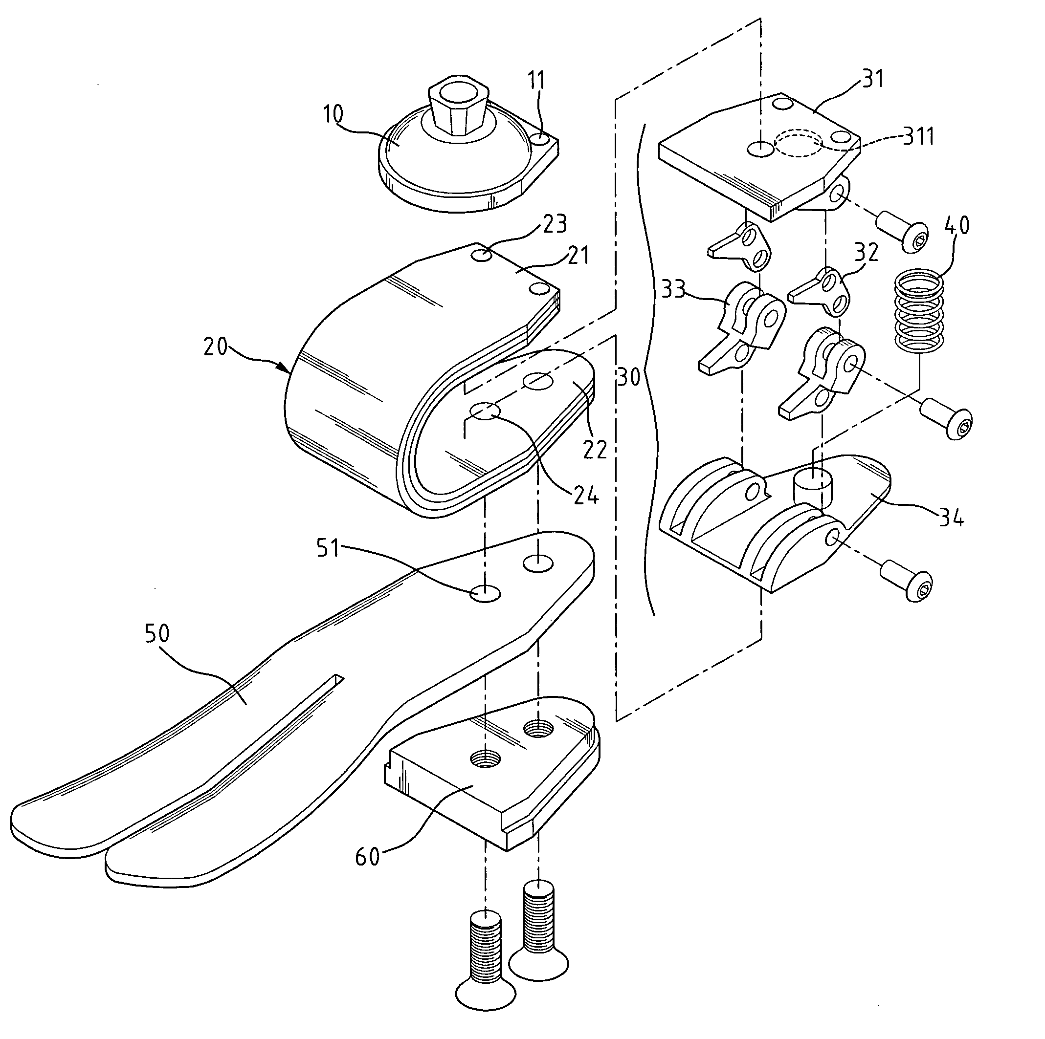
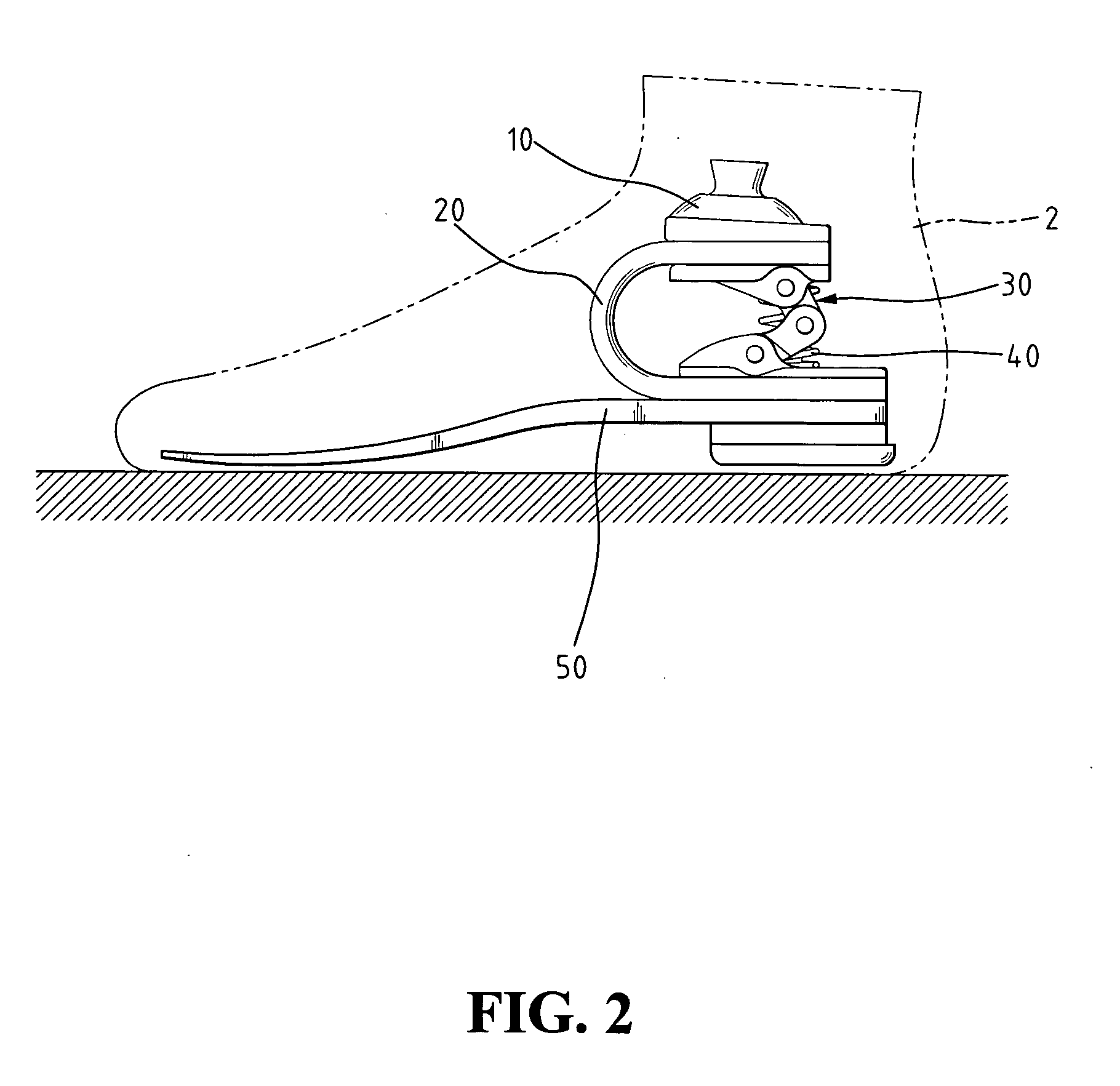
[0016]FIGS. 2 and 3 illustrate an artificial foot, designated with reference numeral 2, constructed in accordance with the present invention. The artificial foot 2 comprises a supporter 10, a holder 20, a linking mechanism 30, an elastic element 40, and a sole 50. A top of the holder 20 is connected with the supporter 10 and a bottom of the holder 20 is fixed with the sole 50. The linking mechanism 30 is provided at a U-shaped space formed by the holder 20. In the embodiment according to the present invention, a real structure of foot is integrally formed, and the holder 20, the elastic element 40, and the linking mechanism 30 are structured into an elastic structure of cushion similar to an ankle in function. In the embodiment according to the present invention, the supporter 10 is upwardly connected to an artificial leg and jointed to a fixing end located therein and the rest are placed into an artistic artificial foot copying features of a real foot so that amputees may have the ...


PUM


Abstract

Disclosed is an elastic energy-stored artificial foot that effectively cushions vibration generated when walking and saves efforts through an energy-stored elasticity by the cushion when walking. The artificial foot includes a supporter supporting an artificial lower leg; a sole of an elastic material; a holder, an elastic plank downward bent to form a U-shaped structure of which an indent faces the back of the foot, and two slabs formed after the holder is bent are an upper connecting plank fixed to the supporter and a lower connecting plank fixed to the sole; an elastic part between the upper connecting plank and the lower connecting plank to provide a buffer capacity after the holder is suppressed; and a linking mechanism between the upper connecting plank and the lower connecting plank to hold a position of the holder compressed to transformation and prevent it from being shifted.

Description

BACKGROUND OF THE INVENTION [0001] 1. Field of the Invention [0002] The present invention relates to an artificial foot, and particularly to an elastic energy-stored artificial foot that effectively cushions vibration induced by waking activity and provides an effort-saving performance through an energy-stored elasticity employed by the elastic cushion when walking. [0003] 2. The Related Art [0004] Referring to FIG. 1, a conventional structure of artificial foot is formed with a body 1 copying a normal structure and function of a foot. The body 1 is equal to a human being's sole of the foot and may be placed into an artistically artificial foot 2 formed and constructed into a real foot. And the body 1 is provided with a supporter 3 to connect with an artificial leg so that amputees may recover an original function of the foot they had using the support of their artificial feet. Consequently, in order to have the structure of artificial foot work and be close to the bones and skeleto...

Claims


Application Information

Patent Timeline
IPC IPC(8): A61F2/66
CPCA61F2/66A61F2002/30359A61F2002/3051A61F2002/5003A61F2002/5038A61F2002/5072A61F2002/6621A61F2002/6642A61F2002/665A61F2002/6671A61F2220/0025A61F2220/0033A61F2002/30507
Inventor HARN, CHUEN-SENZHEN, RUENG-JIE
Owner HARN CHUEN SEN
Why Eureka
Try Eureka