Vacuum released valve

Active Publication Date: 2006-08-10
GOTOHTI COM
View PDF31 Cites 17 Cited by
  • Summary
  • Abstract
  • Description
  • Claims
  • Application Information

AI Technical Summary

Benefits of technology

[0010] Another object is to provide a simple dispenser in which a vacuum released valve for relieving vac

Problems solved by technology

One disadvantage of such arrangements is to prevent spilling or leakage of fluid prior to initiating use of the dispenser.
Such flexible seal members suffer the disadvantage that they are subject to failure, do not always provide a suitable seal, and to be flexible must frequently be made from different materials than the remainder of the value structure.
As well as insofar as a flexible seal member is to be maintained in contact with fluid from the rese

Method used


Image

  • Vacuum released valve
  • Vacuum released valve
  • Vacuum released valve

Examples


Example

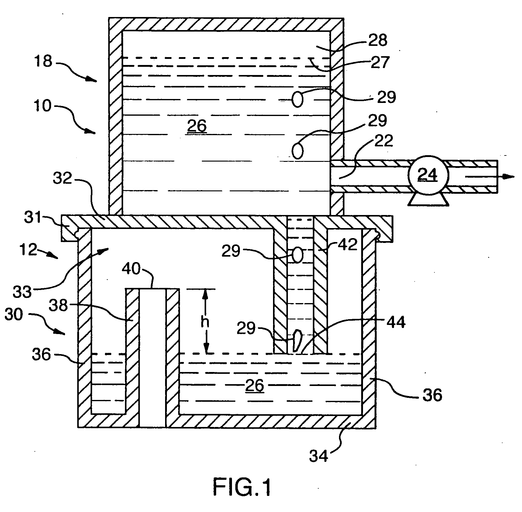
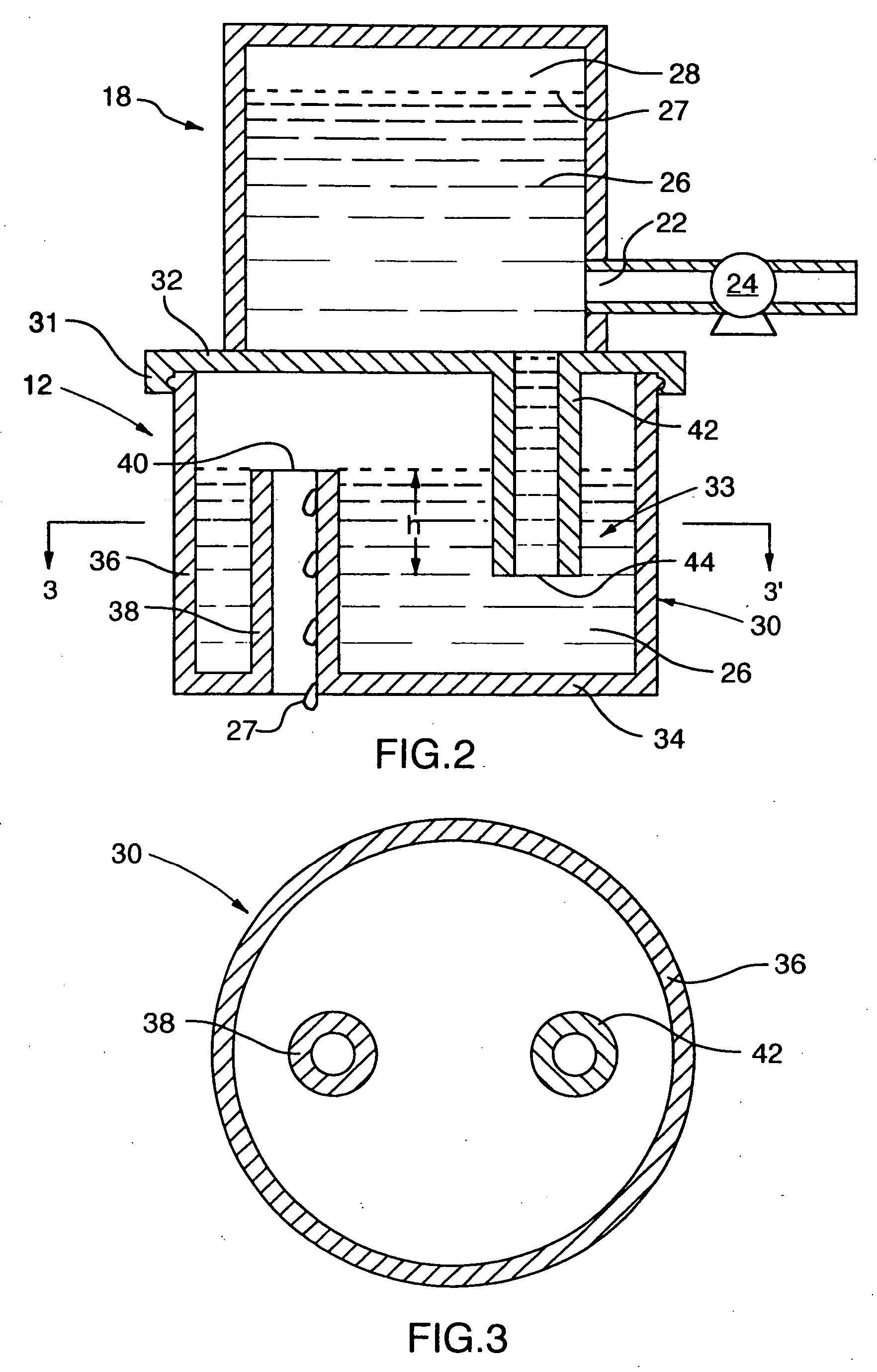
[0065] In the first embodiment of FIGS. 1 to 3, the air inlet 40 is desired to be at a height above the height to which the level of the liquid may, in normal operation, rise in the chamber 33. It is, therefore, a simple matter to determine this height and provide a height to the air inlet 40 which ensures that under reasonable operating conditions that the liquid will not be able to flow from the chamber 33 out the air tube 38.

[0066] Provided the fluid 26 fills the chamber 33 to or above the level of the liquid inlet 44, then air from the chamber 33 is prevented from accessing the liquid inlet 44 and cannot pass through the liquid tube 42 into the reservoir. The ability of liquid 26 to be dispensed out of the reservoir 18 by the pump 26 may possibly be limited to some extent to the degree to which a vacuum may exist in the reservoir. For vacuum to exist in the reservoir, there must be an expandable fluid in the reservoir such as air 28 or other gases above the liquid 26. At any ti...

Example

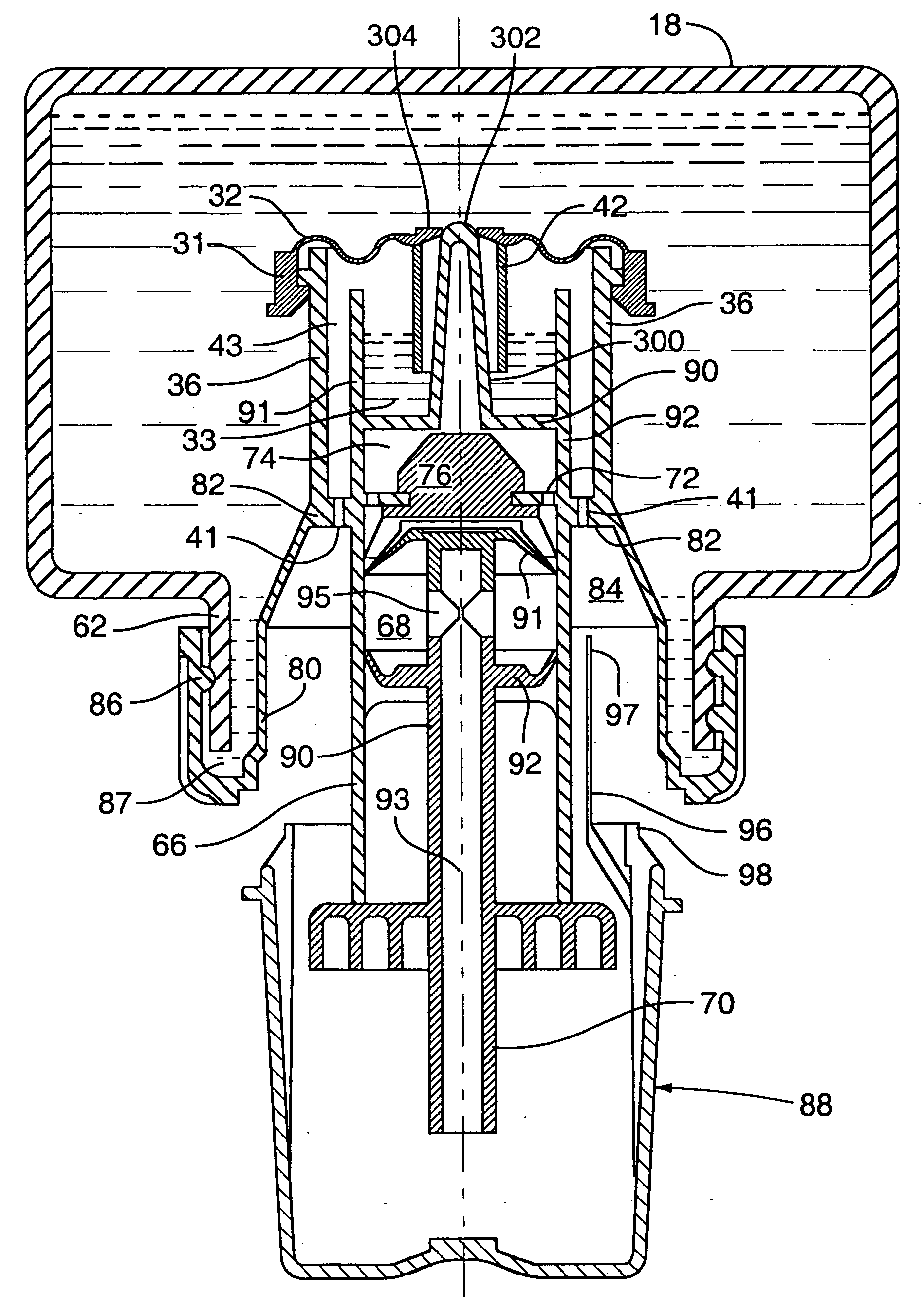
[0068] Reference is made to FIGS. 4 and 5 which show a second embodiment of a vacuum relief device 10 in accordance with the present invention illustrated in a similar schematic arrangement as the first embodiment of FIGS. 1 to 3. The second embodiment has an equivalent to every element in the first embodiment, however, is arranged such that the liquid tube 42 is coaxial with the cap 32 and a cylindrical holding tube 46 extends upwardly from the base 30 concentrically about the liquid tube 42. An air aperture 41 is provided in the base 30 opening into an annular air passageway 43 between the cylindrical side wall 36 and the holding tube 46. Conceptually, as compared to FIG. 1, the effective location and height of the air inlet 40 is at the upper open end of the holding tube 46 which is, of course, at a height above the liquid inlet 44. FIG. 4 shows a condition in which the vacuum in the reservoir 18 is sufficient that the liquid in the holding tube 46 is drawn downwardly to the leve...


PUM


Abstract

These disadvantages of previously known devices, the present invention provides a vacuum released valve which closes an opening into a reservoir to passage therethrough until a sufficient vacuum is created with the reservoir as on initial dispensing of fluid from the reservoir.

Description

RELATED APPLICATIONS [0001] This invention relates to a vacuum relief device and, more particularly, to a vacuum relief mechanism for relieving vacuum developed within a fluid containing reservoir. This application is a continuation-in-part of U.S. application Ser. No. 11 / 085,048 filed Mar. 22, 2005 which is a continuation-in-part of U.S. application Ser. No. 10 / 983,574 filed Nov. 9, 2004 which is a continuation-in-part of U.S. application Ser. No. 10 / 132,321 filed Apr. 26, 2002.SCOPE OF THE INVENTION [0002] This invention relates to a valve and, more particularly, to a valve which is released from a preset condition by vacuum developed within a fluid containing reservoir. BACKGROUND OF THE INVENTION [0003] Arrangements are well known by which fluid is dispensed from fluid containing reservoirs. One disadvantage of such arrangements is to prevent spilling or leakage of fluid prior to initiating use of the dispenser. For example, known hand soap dispensing systems provide rigid reser...

Claims


Application Information

Patent Timeline
IPC IPC(8): B67D1/08
CPCA47K5/1202A47K5/1211A47K5/122
Inventor OPHARDT, HEINER
Owner GOTOHTI COM
Why Eureka
Try Eureka