Eureka AIR delivers breakthrough ideas for toughest innovation challenges, trusted by R&D personnel around the world.

Apparatus for and method of dispensing chemical solution in spin-coating equipment

a technology of spin coating and apparatus, which is applied in the direction of photomechanical equipment, instruments, coatings, etc., can solve the problems of high and high maintenance cost of the conventional dispensing apparatus. achieve the effect of substantially uniform dispensing of chemical solution and low cos

Active Publication Date: 2012-03-20
SAMSUNG ELECTRONICS CO LTD
View PDF9 Cites 9 Cited by
  • Summary
  • Abstract
  • Description
  • Claims
  • Application Information

AI Technical Summary

Benefits of technology

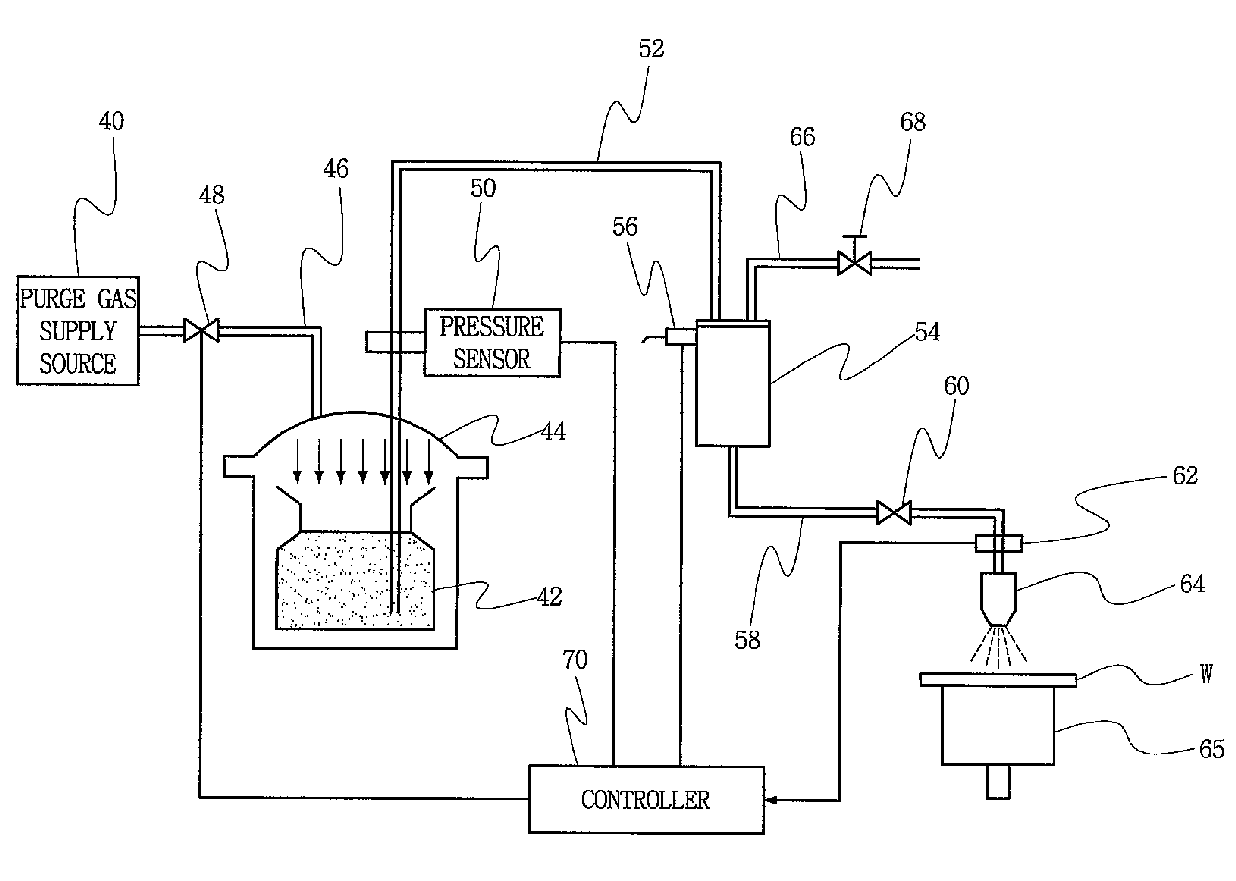
[0018]An object of the present invention is to provide apparatus for dispensing a chemical solution in spin-coating equipment, which is relatively inexpensive, has low costs associated with the maintenance thereof, and yet can dispense the chemical solution substantially uniformly.
[0019]Another object of the present invention is to provide a method of and apparatus for dispensing a chemical solution in spin-coating equipment, which can dispense the chemical solution substantially uniformly and in a relatively short amount of time, i.e., which are highly efficient.
[0020]A more specific object of the present invention is to provide a method of and apparatus for dispensing a chemical solution in spin-coating equipment, which obviate the need for expensive components such as a fluid pump and three-way valve.
[0024]In accordance with another aspect of the present invention, the dispensing apparatus also has means for preventing the chemical solution from being dispensed while bubbles are entrained in the solution. In this respect, the trap has an exhaust line connected to an upper end of the tank, and a vent valve disposed in the exhaust line. Thus, air in the tank can be vented through the exhaust line and vent valve. Also, a bubble sensor is operatively associated with the second chemical supply line so as to sense whether bubbles are present in chemical solution flowing through the second chemical supply line towards the nozzle. The controller is operatively connected to the bubble sensor so as to generate an interlock signal that stops the operation of the dispensing apparatus when bubbles are sensed by the bubble sensor.

Problems solved by technology

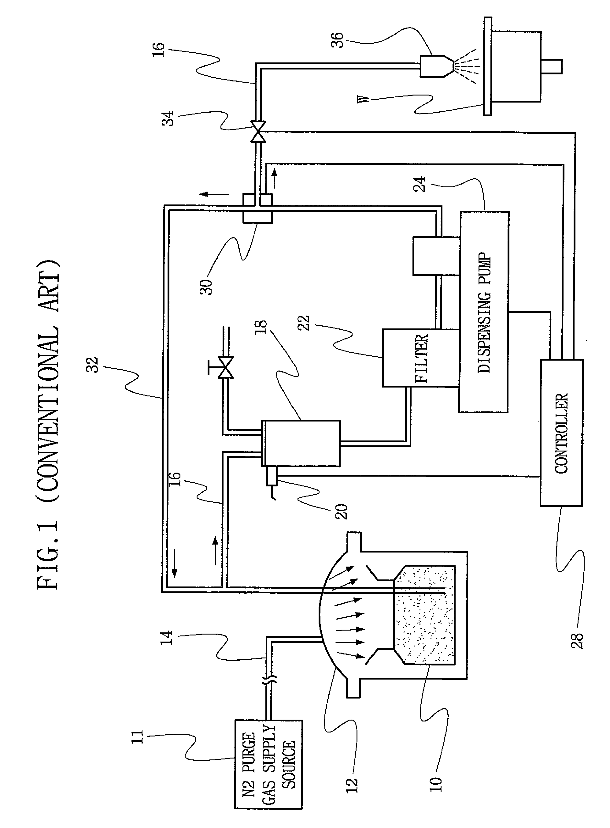
The conventional dispensing apparatus described above is expensive to manufacture.
In particular, the dispensing pump 24 and the three way valve 30 are very expensive components.
Accordingly the maintenance costs associated with the conventional dispensing apparatus are also relatively high.
Moreover, the conventional dispensing apparatus takes a long time to empty the bottle 10 in dispensing the solution onto wafers.
Thus, the conventional dispensing apparatus is rather inefficient.

Method used


Image

  • Apparatus for and method of dispensing chemical solution in spin-coating equipment
  • Apparatus for and method of dispensing chemical solution in spin-coating equipment
  • Apparatus for and method of dispensing chemical solution in spin-coating equipment

Examples


Embodiment Construction

[0029]The present invention will now be described more fully hereinafter with reference to the accompanying drawings. However, those portions of the present invention which are well-known per se will not be described in detail so as not to obscure the gist of the present invention.

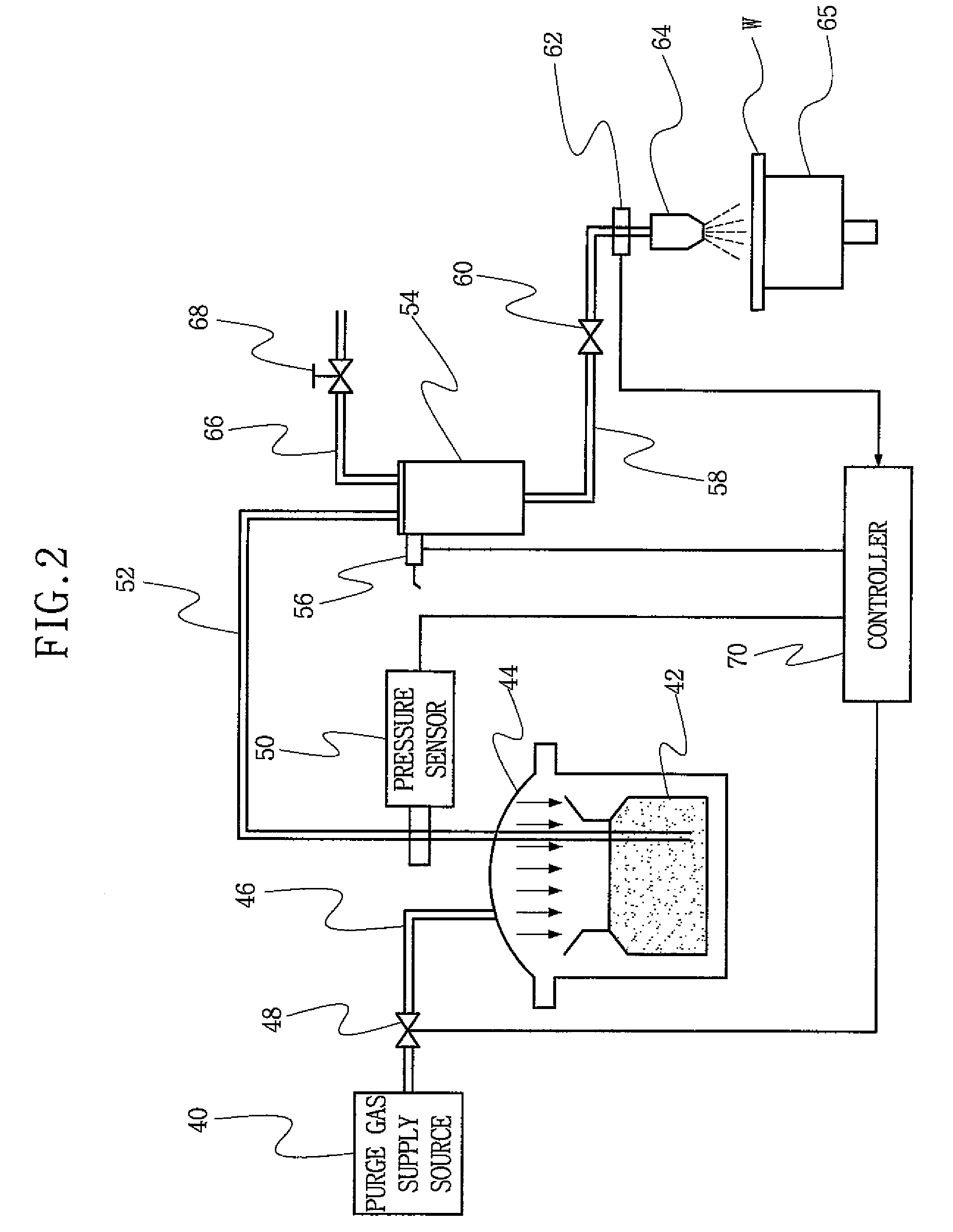
[0030]Referring to FIG. 2, apparatus for dispensing a chemical solution (a fluid) according to the present invention includes an N2 purge gas supply source 40 comprising a source of N2, a canister 44 configured to receive a bottle 42 containing the chemical solution to be dispensed, gas supply piping 46 connecting the gas supply source 40 to the canister 44 so that N2 can be supplied into the canister 44, a pressure control valve 48 disposed in the gas supply piping 46 and controllable to regulate the pressure of the N2 supplied into the canister 44, a first chemical supply line 52 extending from the bottle 42 within the canister 44, and a pressure sensor 50 operatively associated with the first chemical s...


PUM

PropertyMeasurementUnit
pressureaaaaaaaaaa
timeaaaaaaaaaa
pressureaaaaaaaaaa

Abstract

A chemical solution is uniformly dispensed from a nozzle by N2 in spin-coating equipment. The dispensing apparatus includes a canister configured to receive a bottle containing the chemical solution, gas supply piping connecting a source of N2 to the inside of the canister, a pressure control valve disposed in the gas supply piping, a chemical supply line by which the bottle is connected to the nozzle, a pressure sensor for sensing the pressure of the chemical solution supplied from the bottle, and a controller that controls the pressure control valve on the basis of the pressure sensed by the pressure sensor. The controller opens the pressure control valve further when the value of the signal output by the pressure sensor is less than a value representative of the minimum of a predetermined pressure range, and closes the pressure control valve further when the value of the signal output by the pressure sensor is greater than a value representative of the maximum of the predetermined pressure range. The degree to which the pressure control is open is thus controlled by feedback from the pressure control sensor such that the pressure of the chemical solution remains substantially constant as it is dispensed from the nozzle.

Description

BACKGROUND OF THE INVENTION[0001]1. Field of the Invention[0002]The present invention relates to spin-coating equipment for coating a substrate with a chemical solution such as a photoresist solution. More particularly, the present invention relates to a method of and apparatus for dispensing chemical solution onto a substrate in spin-coating equipment.[0003]2. Discussion of Related Art[0004]In general, the manufacturing of semiconductor devices includes fabrication, assembly and test processes. The fabrication processes involve processing a substrate, e.g., a polished silicon wafer, and include diffusion, thin-film formation, photolithography, and etching processes which are each well-known per se. These fabrication processes are repeatedly and selectively performed on the wafer to form electronic circuitry. Thus, the semiconductor device fabrication processes form an intermediate product which is later packaged, through an assembly process, and tested.[0005]Among the aforementione...

Claims


Application Information

Patent Timeline
Patent Type & Authority Patents(United States)
IPC IPC(8): B05C11/00B05B15/02B05C5/00B05C11/02
CPCB05C11/1013B05C11/08G03F7/162H01L21/67253H01L21/00
Inventor CHO, SEUNG-KI
Owner SAMSUNG ELECTRONICS CO LTD
Why Eureka
Eureka Blog
Learn More