Can and bottle dispenser

a dispenser and canister technology, applied in the field of can and bottle dispensers, can solve the problems of not pleasing the appearance of the refrigerator, not suitable for in-home use, known vending machines,

Inactive Publication Date: 2006-12-26
MAYTAG
View PDF81 Cites 11 Cited by
  • Summary
  • Abstract
  • Description
  • Claims
  • Application Information

AI Technical Summary

Benefits of technology

[0009]According to another feature of the present invention a dispenser has a hinge that facilitates the installation and removal of a door from a cabinet. The hinge includes a male portion and a female portion for mated engagement with the male portion. One of the portions of the hinge is attached to the door and the other portion is attached to cabinet such that the male and female portions can be taken out of mated engagement by lifting the door until the male portion is clear from the female portion. A tab is attached to the door. A catch is attached to the cabinet such that the catch interferes with the tab to prevent lifting the door if the door is closed, but permits lifting the door if the door is opened a sufficient amount. A sufficient amount may be approximately ninety degrees. Preferably the hinge is strong enough that the dispenser can be lifted using the door when the door is closed without the door being separated from the cabinet.
[0014]According to another embodiment of the present invention a dispenser prevents the dispensing of a second item until a first item has moved completely into a dispensing area. The dispenser includes a cabinet having an enclosed area containing items to be dispensed. An accessible dispensing are is provided. A dispensing mechanism is provided to move the items to be dispensed from the enclosed area to the dispensing area. A barrier is provided between the dispensing area and the enclosed area. The barrier is biased to a closed position that substantially covers an opening between the dispensing area and the enclosed area. The barrier is movable to an open position by a weight of a dispensed item pressing against the barrier. A sensor is provided to sense when the barrier has moved to an open position and for preventing a second selected from being dispensed until the barrier has returned to a closed position.
[0015]According to another embodiment of the present invention a dispenser has an illuminated dispensing area that is illuminated for a short period of time after an item is dispensed. The dispenser includes a cabinet containing items to be dispensed in an enclosed area. A dispensing area is located externally to the cabinet. A light source is provided to at least partially illuminate the dispensing area. A barrier is provided between the enclosed area and the dispensing area. The barrier is biased towards a normally closed position. The barrier is movable to an open position by the weight of a selected item moving from the enclosed area to the dispensing area. A sensor is provided for sensing when the barrier has moved from the open position to the closed position. A mechanism is provided for illuminating the dispensing area for a specified period of time after the barrier has moved from the open position to the closed position.

Problems solved by technology

In some instances the appearance of these refrigerators is not pleasing.
However, known vending machines have several drawbacks that them make ill-suited for in-home, or other noncommercial use.
The vending machines have security and payment features that are unnecessary and cumbersome in many instances.

Method used


Image

  • Can and bottle dispenser
  • Can and bottle dispenser
  • Can and bottle dispenser

Examples


Embodiment Construction

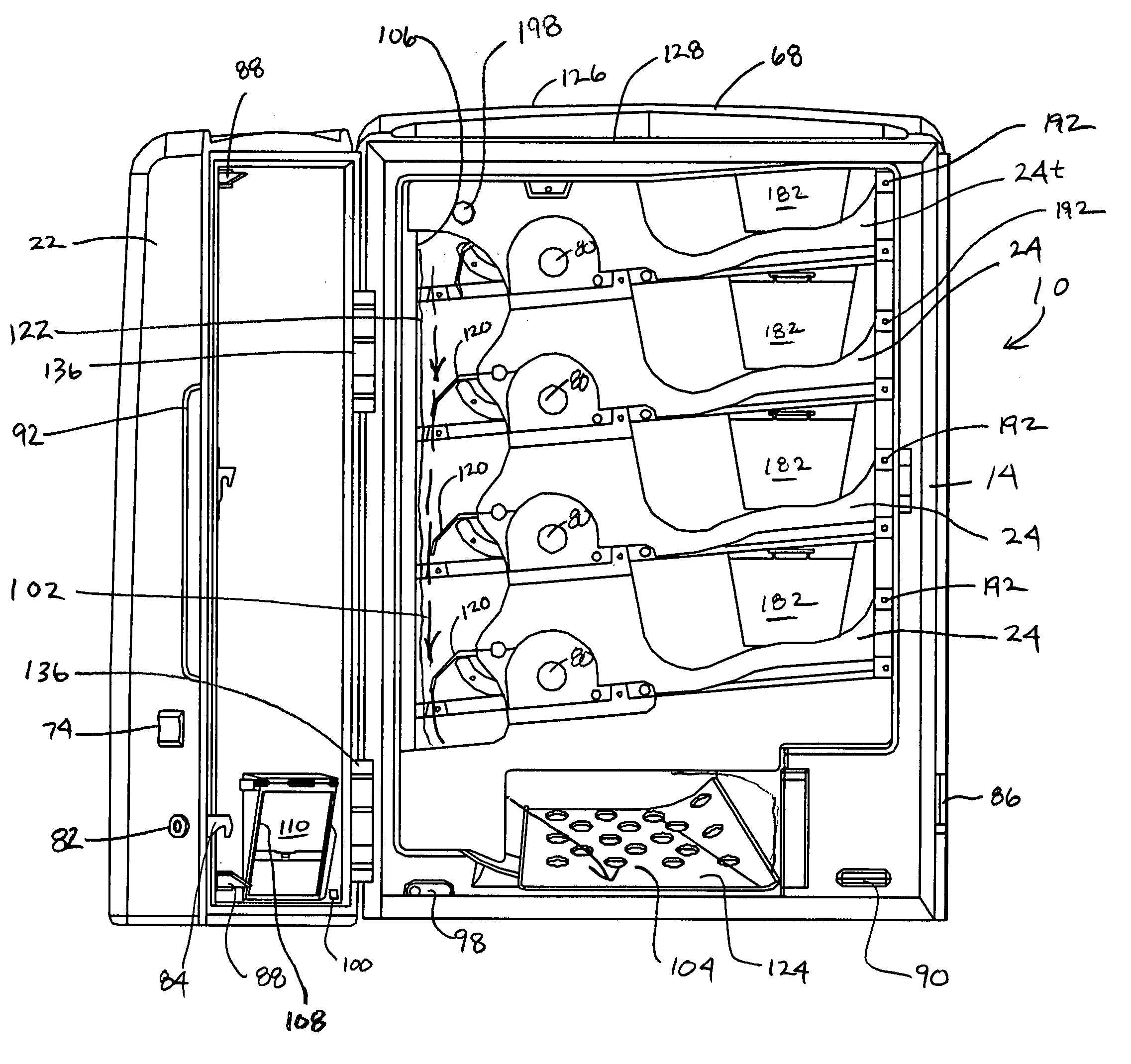
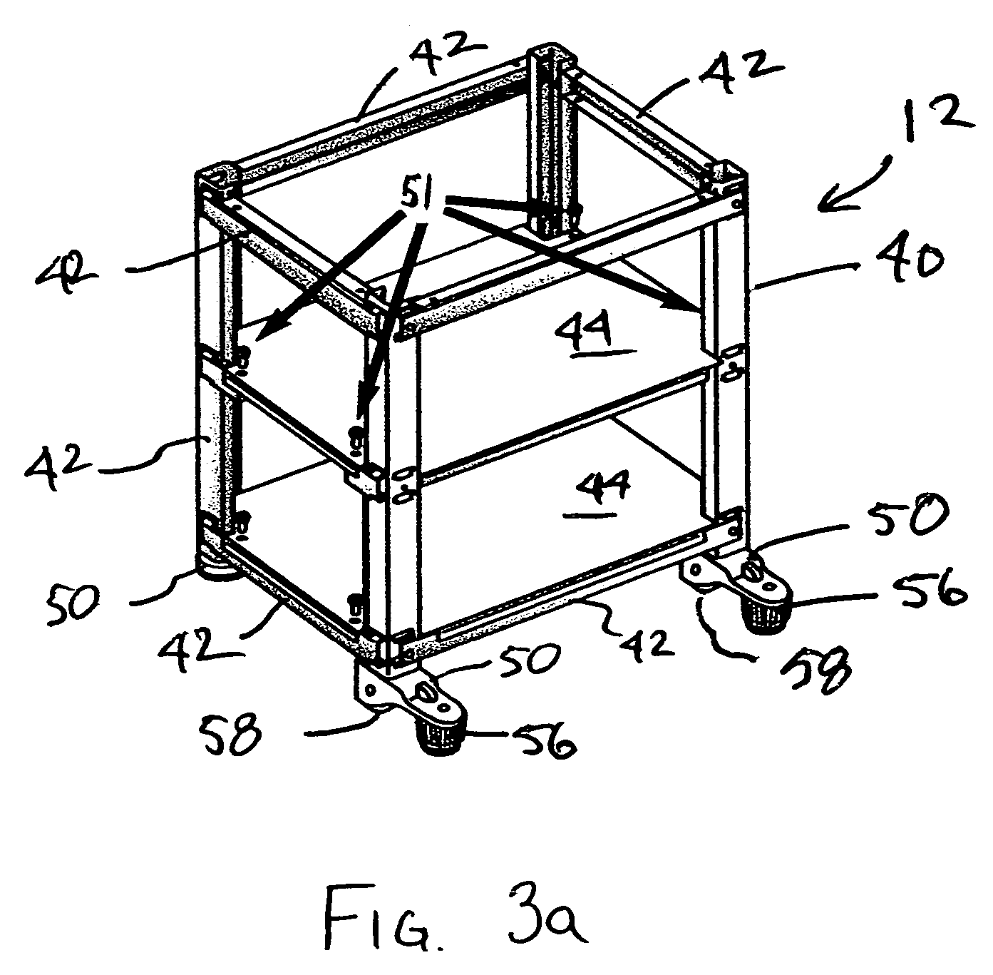
[0046]Shown generally in the drawings and described below are various embodiments of a dispenser 10. The preferred use of the dispenser 10 is as a personal beverage dispenser in a home or office. It has several preferred features. Notably the dispenser 10 need not be provided with a coin or other money receptacle, and it is intended to vend items without the insertion of any money, or other payment. Many of the features of the dispenser 10 would be well suited for use in traditional for-money vending machines. The dispenser 10 is designed to be able to dispense both cans and bottles without changing the configuration, or adding additional parts. As seen in the figures, the vending unit may be used free-standing, or may be placed on a matching stand 12. Preferably, the unit will include accommodations for attaching a removable display or sign, such as a logo for a team, race car driver, or other decoration.

[0047]FIG. 1 shows an embodiment of a dispenser 10 according to the present in...


PUM


Abstract

A coupling for connection of a tube comprises a coupling housing which includes a first end into which the tube is inserted, a clamping ring which is positioned in the coupling housing against a first conical surface, a sealing ring which is positioned in the coupling housing, and a return ring which is positioned in the coupling housing between the clamping ring and a second end of the housing adjacent a second conical surface that is tapered opposite to the first conical surface. The return ring is expandable and comprises a central aperture which is smaller than the external diameter of the tube. Accordingly, when the tube is pushed into the coupling housing and forced through the return ring, the return ring will expand and move along the second conical surface.

Description

[0001]This application claims the benefit of related U.S. Provisional Application Ser. No. 60 / 487,468, filed on Jul. 14, 2003 and U.S. Provisional Application Ser. No. 60 / 540,632, filed on Jan. 30, 2004, which applications are hereby incorporated by reference.FIELD OF INVENTION[0002]The present invention generally involves the field of can and bottle dispensers, and more particularly involves a vending-machine-like dispenser for dispensing bottles and cans that is suitable for use in a home or office.BACKGROUND[0003]Many homes and offices have refrigerators that are dedicated primarily or exclusively to holding bottles and cans of beverages. In some instances the appearance of these refrigerators is not pleasing. In many regards, the appearance and functionality of a vending machine would be preferable to a standard refrigerator. In particular, it would be desirable for the beverage refrigerators to be able to selectively dispense a single can or bottle without opening the refrigera...

Claims


Application Information

Patent Timeline
Patent Type & Authority Patents(United States)
IPC IPC(8): G07F11/16A24F27/14A47F1/04A47F1/10A47F7/28B65DB65H1/00G07F9/02G07F11/28G07F11/32
CPCA47F1/10A47F7/28G07F9/026G07F11/28G07F11/32
Inventor HUFFER, DOUGLOWERY, FREDPETERSEN, GARYGAUSMANN, KEITHMARINO, SAMUELMYERS, GARYFLOAT, JAMISON J.PERKINS, JAY F.PEVER, STEVEHAYES, ROBERTKOPCZEWSKI, MICHAEL T.HSU, PAUL E.SCHAEFER, DOUGLAS G.BURCHFIELD, BRENT L.DEBORD, JEFFREY T.
Owner MAYTAG
Why Eureka
Try Eureka