Plasma display panel using color filters to improve contrast

a technology of color filters and display panels, applied in the field of plasma display panels, can solve the problems of reducing the contrast in the bright room, and achieve the effect of improving contras

Inactive Publication Date: 2006-08-10
SAMSUNG SDI CO LTD
View PDF15 Cites 25 Cited by
  • Summary
  • Abstract
  • Description
  • Claims
  • Application Information

AI Technical Summary

Benefits of technology

[0009] The present invention provides a plasma display panel (PDP) with improved contrast.

Problems solved by technology

However, in the PDP, bright room contrast is reduced due to the brightness of external light reflected off the PDP.

Method used


Image

  • Plasma display panel using color filters to improve contrast
  • Plasma display panel using color filters to improve contrast
  • Plasma display panel using color filters to improve contrast

Examples


Embodiment Construction

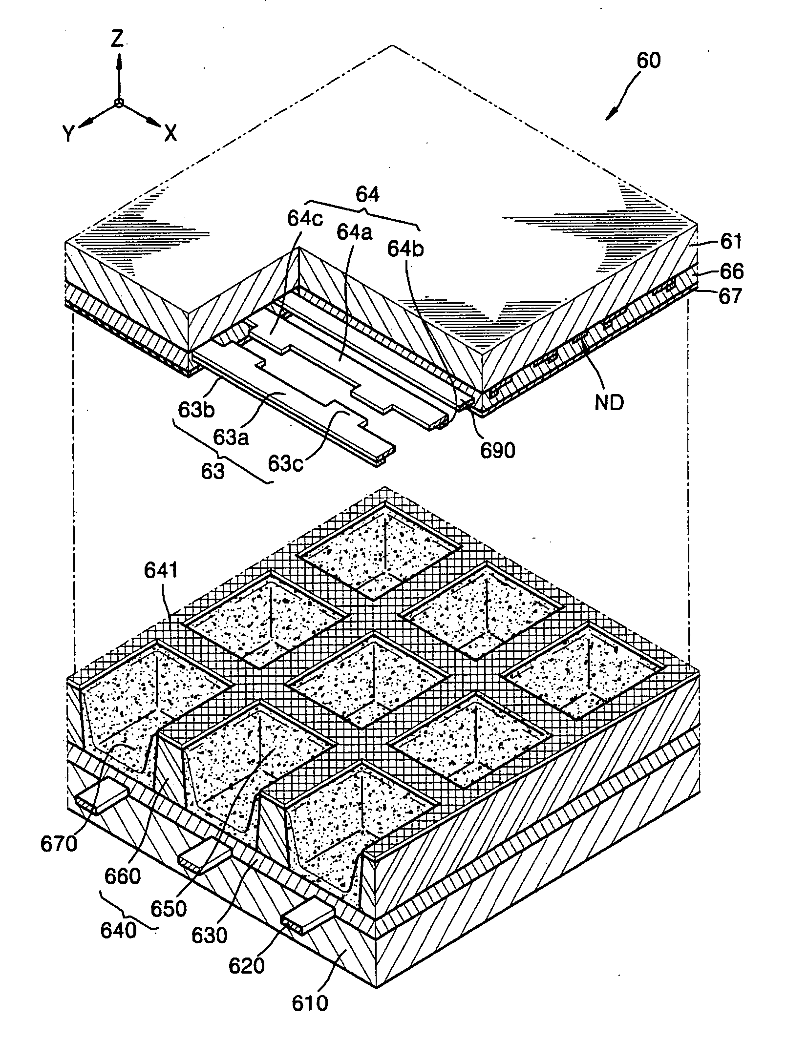
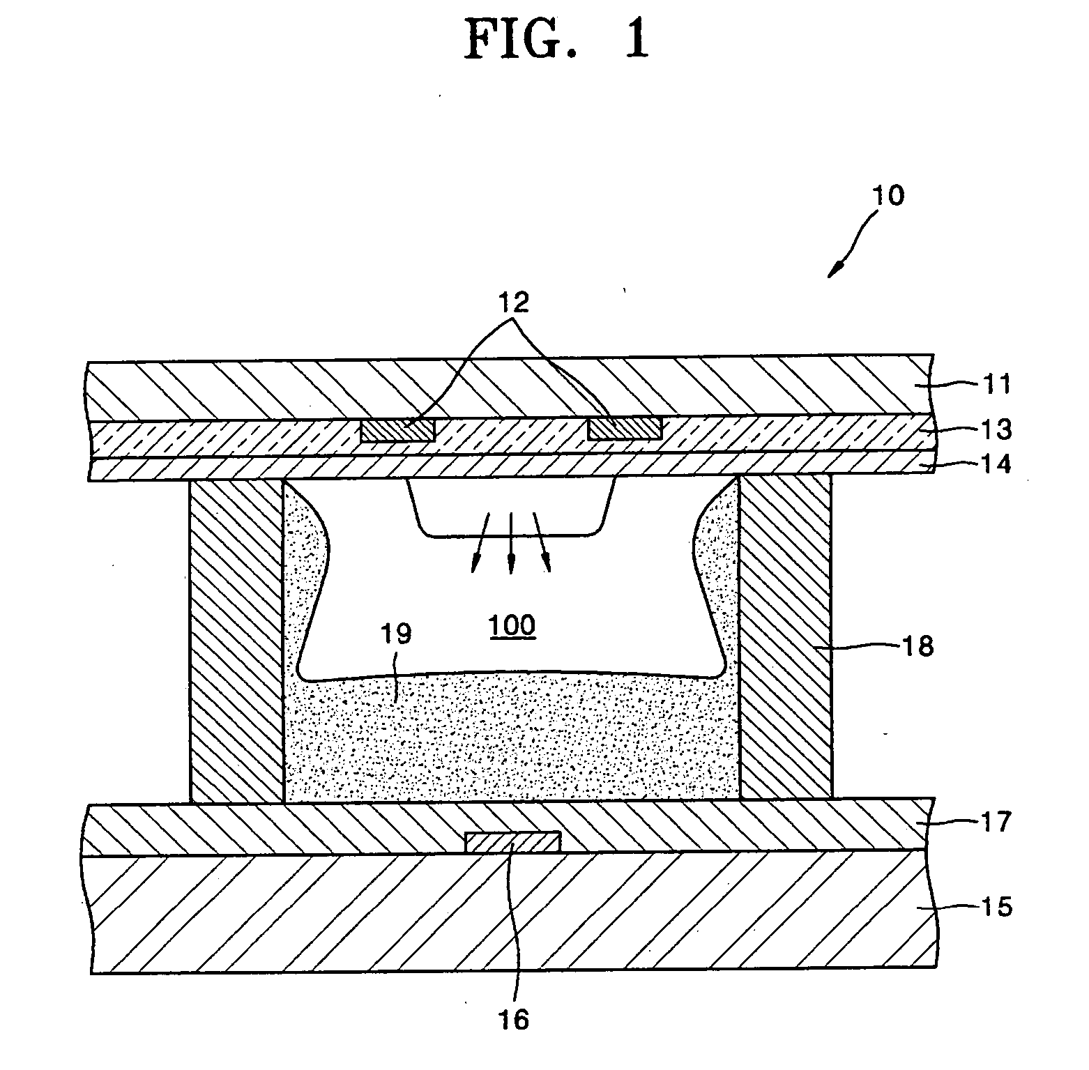
[0022] Turning now to the figures, FIG. 1 is a cross-sectional view of a unit cell of a PDP 10. Referring to FIG. 1, the PDP 10 includes a pair of sustaining electrodes 12 on a front substrate 11 and a front dielectric layer 13 covering the pair of sustaining electrodes 12. A surface of the front dielectric layer 13 is coated with a protective layer 14.

[0023] Address electrodes 16 are formed on a rear substrate 15 installed to face the front substrate 11, a rear dielectric layer 17 is formed on the address electrodes 16, barrier ribs 18 are formed on the rear dielectric layer 17, and red, green, and blue fluorescent layers 19 are formed to cover an upper surface of the rear dielectric layer 17 and inner sidewalls of the barrier ribs 18. The front substrate 11 is combined with the rear substrate 15, an inert gas is injected into an inner gap between the front and the rear substrates 11 and 15, thus forming a discharge region 100 therebetween.

[0024] An operation of the PDP 10 with t...


PUM


Abstract

A plasma display panel is provided. The plasma display panel includes a front substrate; a rear substrate arranged to face the front substrate, a dielectric layer arranged between the front and the rear substrates and at least a portion of the dielectric layer having a first color, plurality of barrier ribs arranged between the front and the rear substrates and at least a portion of the plurality of barrier ribs having a second color, plurality of light absorbing layers arranged between the front substrate and the plurality of barrier ribs, wherein the first and the second colors are subtractive-mixed with each other. The dielectric layer and the plurality of barrier ribs are colored with two complementary colors that essentially filter out nearly all light. Accordingly, it is possible to reduce outdoor daylight reflection and improve image contrast

Description

CROSS-REFERENCE TO RELATED APPLICATIONS [0001] This application is a Continuation-in-Part of U.S. patent application Ser. No. 10 / 915,597 entitled PLASMA DISPLAY PANEL, filed 11 Aug. 2004 in the U.S. Patent & Trademark Office.CLAIM OF PRIORITY [0002] This application makes further reference to, incorporates the same herein, and claims all benefits accruing under 35 U.S.C §119 from an application entitled PLASMA DISPLAY PANEL filed in the Korean Industrial Property Office on May 24, 2000, and there duly assigned Serial No. 2003-56849 by that Office. BACKGROUND OF THE INVENTION [0003] 1. Field of the Invention [0004] The present invention relates to a plasma display panel (PDP), and more particularly, to a PDP which reduces the brightness of outdoor daylight reflection using a complementary color relationship between a dielectric layer and barrier rib as opposed to using black stripes. [0005] 2. Description of the Related Art [0006] In general, a plasma display panel (PDP) displays num...

Claims


Application Information

Patent Timeline
Patent Type & Authority Applications(United States)
IPC IPC(8): H01J17/49H01J11/12H01J11/22H01J11/24H01J11/26H01J11/34H01J11/36H01J11/38
CPCH01J11/12H01J11/44H01J2211/36H01J2211/38H01J2211/444H01J11/38H01J11/36
Inventor YOO, SUNG-HUNEKWEON, TAE-JOUNG
Owner SAMSUNG SDI CO LTD
Why Eureka
Try Eureka