
Method and apparatus for testing liquid crystal display device

a liquid crystal display and display device technology, applied in measurement devices, electrical testing, instruments, etc., can solve the problems of defective substrates, large weight and volume, undesirable ratios and waste materials,

Inactive Publication Date: 2006-08-10
LG DISPLAY CO LTD
View PDF12 Cites 13 Cited by
  • Summary
  • Abstract
  • Description
  • Claims
  • Application Information

AI Technical Summary

Benefits of technology

The present invention provides a method and apparatus for testing LCD display devices by using an inspection apparatus that can detect defects quickly and accurately without requiring a jig. The inspection apparatus includes a light source, inspection lines, and inspection switch devices that are connected to the inspection lines. The method involves radiating light onto the inspection switch devices and charging a voltage onto the capacitors formed in the effective display area of the substrate. The charged voltage is then read to determine if there is a defect in the effective display area. The invention also provides a method for inspecting the substrate of a liquid crystal display device by using an inspection apparatus that can be easily removed after inspection. The technical effects of the invention include improved efficiency and accuracy in detecting defects and the ability to inspect the substrate of a liquid crystal display device without attaching driving circuits.

Problems solved by technology

Among the display apparatuses, a cathode ray tube is widely used at present, but is disadvantageous in that its weight and volume are large.
Specifically, the electrical inspection of the signal wirings of the TFT array substrate and the pixel electrode of the lower substrate performed before the substrate assembling process may reduce an undesirable ratio and a waste matter and may find a defective substrate capable of repairing at an early stage.
However, in the inspecting process, defective substrates beyond repair are discarded.
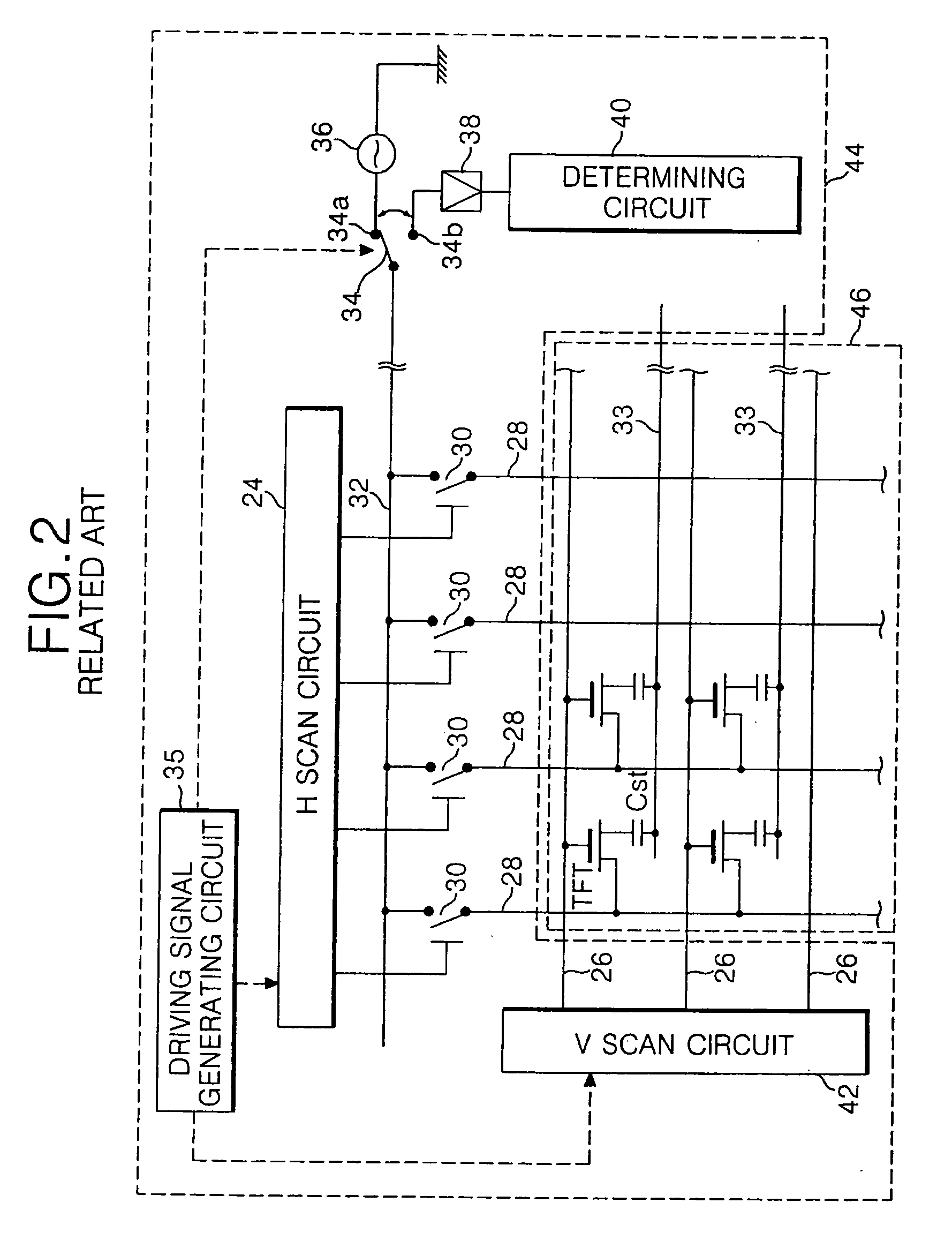
As a result, there is a problem that the inspection device of the related art shown in FIG. 2 needs a high price jig.
However, there is another problem that a defect location within the block cannot be detected with precision.

Method used


Image

  • Method and apparatus for testing liquid crystal display device
  • Method and apparatus for testing liquid crystal display device
  • Method and apparatus for testing liquid crystal display device

Examples


Embodiment Construction

[0042] Reference will now be made in detail to the preferred embodiments of the present invention, examples of which are illustrated in the accompanying drawings.

[0043] Hereinafter, as referring to FIGS. 3 to 8, the preferred embodiments of the present invention will be explained in full detail.

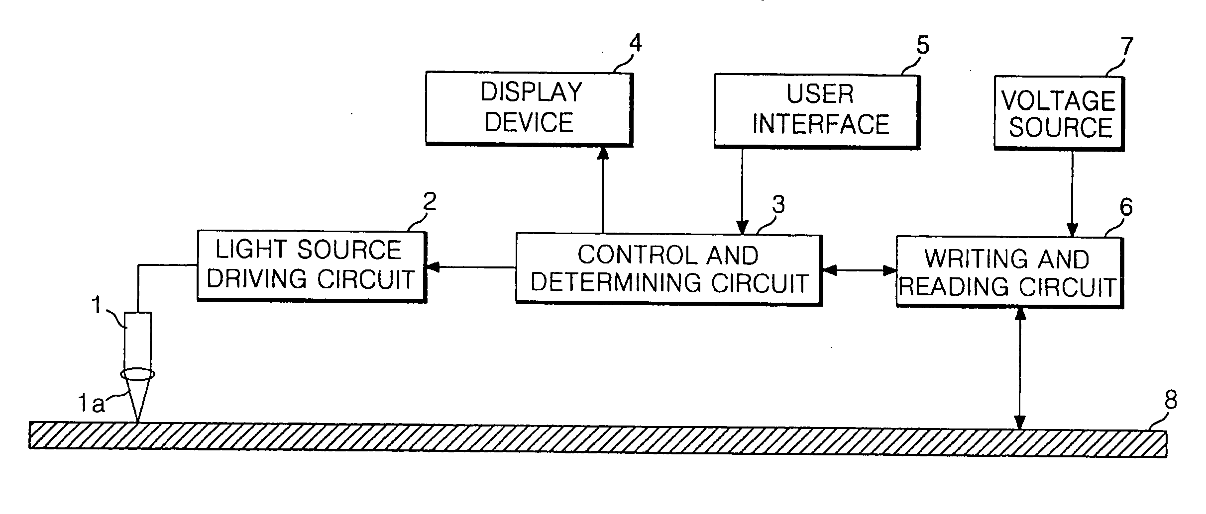
[0044] Referring to FIG. 3, an inspection device for a liquid crystal display according to a preferred embodiment of the present invention includes a light source 1 for radiating a light 1a on a substrate 8 to be inspected, a writing and reading circuit 6, a voltage source 7 for supplying an inspection voltage to the writing and reading circuit 6, a light source driving circuit 2 for driving the light source 1, a display device 4, and a controlling and determining circuit 3 for controlling a user interface device 5. All the components of the inspection device are operatively coupled. The substrate 8 includes a TFT array formed thereon and is part of a liquid crystal display device.

[0045] T...


PUM

PropertyMeasurementUnit
areasaaaaaaaaaa
weightaaaaaaaaaa
volumeaaaaaaaaaa

Abstract

A method and apparatus for testing a liquid crystal display device are provided to detect a defect location precisely and rapidly without requiring a jig. The method includes providing an inspection apparatus as a removable portion of the liquid crystal display device; inspecting the display part of the liquid crystal display device using the inspection apparatus; removing the inspection apparatus from the liquid crystal display device after the inspection is completed; and attaching driving circuits to the liquid crystal display device having the inspection apparatus removed therefrom.

Description

[0001] This application is a Divisional of co-pending application Ser. No. 10 / 669,460, filed on Sep. 25, 2003, the entire contents of which are hereby incorporated by reference and for which priority is claimed under 35 U.S.C. §120. The present application claims, under 35 U.S.C. § 119, the priority benefit of Korean Patent Application No. P2003-28644, filed May 6, 2003, the entire contents of which are herein fully incorporated by reference.BACKGROUND OF THE INVENTION [0002] 1. Field of the Invention [0003] The present invention relates in general to a liquid crystal display (LCD) device and, more particularly, to a method and apparatus for testing an LCD device to detect a defective location on the LCD device precisely and rapidly without requiring a jig. [0004] 2. Description of the Related Art [0005] Display apparatuses have become important as visual information transferring media. Among the display apparatuses, a cathode ray tube is widely used at present, but is disadvantageo...

Claims


Application Information

Patent Timeline
Patent Type & Authority Applications(United States)
IPC IPC(8): G01R31/00G02F1/13G02F1/1362G09G3/00G09G3/36
CPCG02F1/1303G02F1/136213G02F1/136259G02F2001/136254G02F2001/136268G02F2203/69G09G3/006G09G3/3648G09G2300/0426G02F1/136254G02F1/136268G02F1/13
Inventor KIM, JONG DAMLEE, HYUN KYUCHO, YONG JINJEONG, SEE HWA
Owner LG DISPLAY CO LTD
Learn More