
Sensor arrangement for the climate control of a motor vehicle

a technology for motor vehicles and sensors, applied in the direction of instruments, heat measurement, heating types, etc., can solve the problem of insufficient control of interior temperature, and achieve the effect of precise and faster detection of measured values

Active Publication Date: 2010-11-30
PREH GMBH
View PDF18 Cites 5 Cited by
  • Summary
  • Abstract
  • Description
  • Claims
  • Application Information

AI Technical Summary

Benefits of technology

[0008]It is therefore an object of the invention to provide a sensor arrangement, which enables miniaturization of the sensor and at the same time provides for a more precise and more rapid detection of the measured values without use of a sensor ventilator unit, i.e., active sensor ventilation. In addition, interfering effects by heat sources affecting the sensor are eliminated.
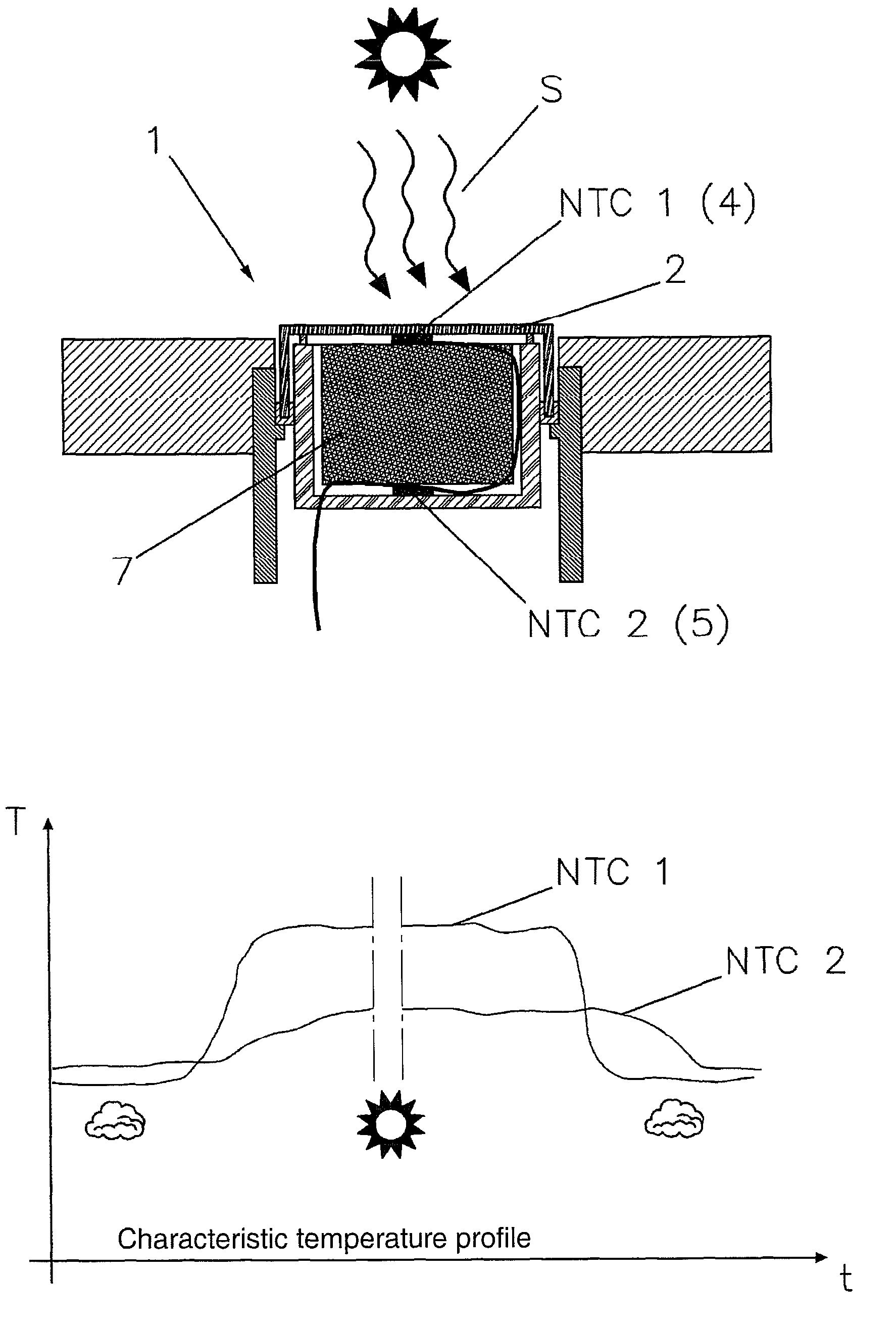
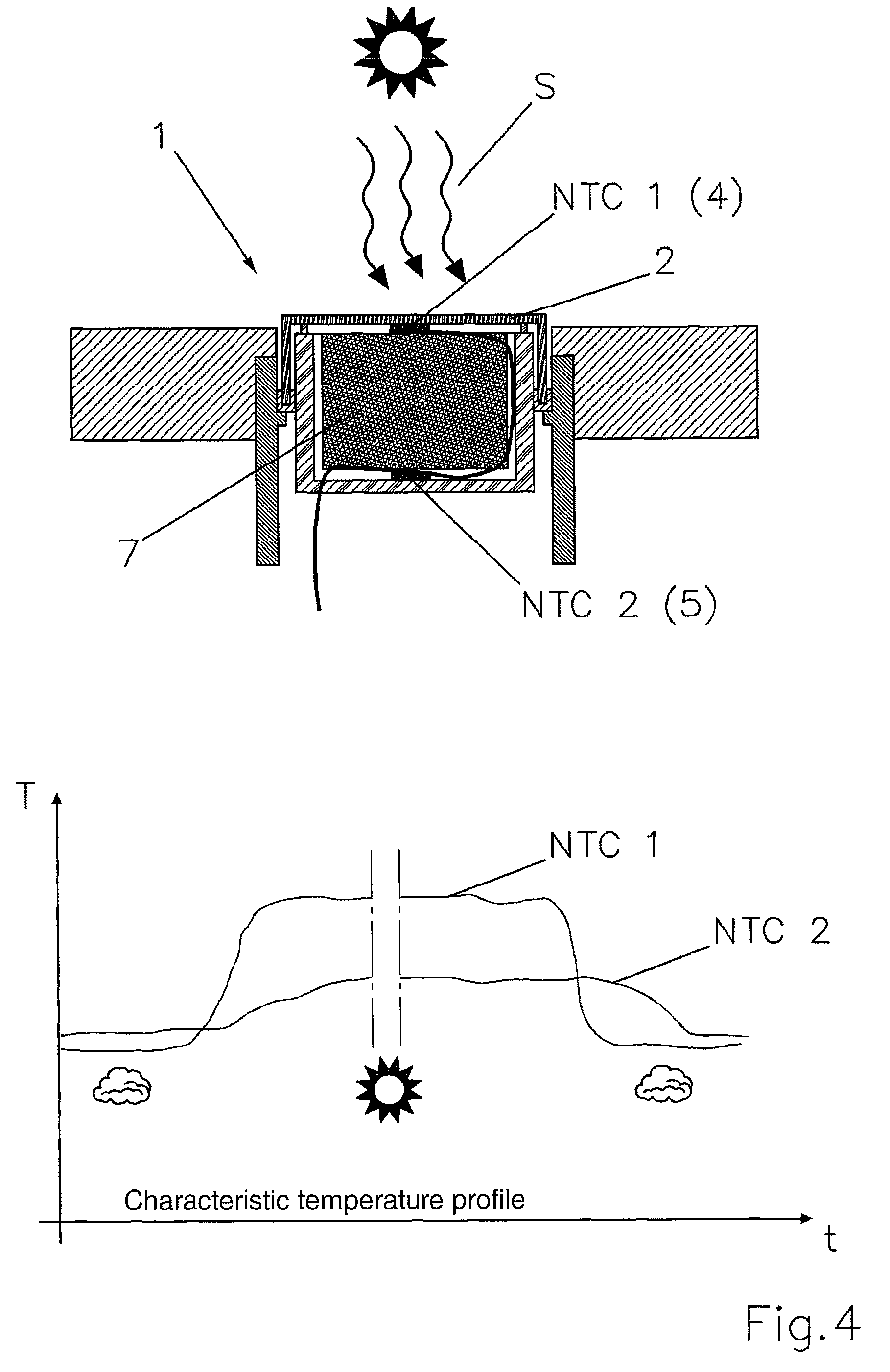
[0009]In an embodiment, at least a second temperature sensor in the sensor arrangement is attached to an inner side of the rear wall, the side facing the back of the front wall. By attaching an at least second temperature sensor in the interior of the housing of the sensor arrangement, heat sources, radiating backward onto the sensor arrangement, are detected in terms of temperature, evaluated in downstream evaluation electronics, and used for a more accurate detection of the interior temperature. In contrast to the conventional art, the direct heating of the housing of the sensor arrangement is detected hereby, from which the actual heat radiation on the first temperature sensor can be detected. By integration into the housing and detection of the backward radiation of the rear wall of the housing, on the one hand, rapid adjustment of the first temperature sensor is possible and the sensor arrangement can be dimensioned a great deal smaller in its dimensions.

Problems solved by technology

Thus, in particular, direct solar radiation on the sensor arrangement can falsify the measured values, which in turn results in insufficient control of the interior temperature.

Method used


Image

  • Sensor arrangement for the climate control of a motor vehicle
  • Sensor arrangement for the climate control of a motor vehicle
  • Sensor arrangement for the climate control of a motor vehicle

Examples


Embodiment Construction

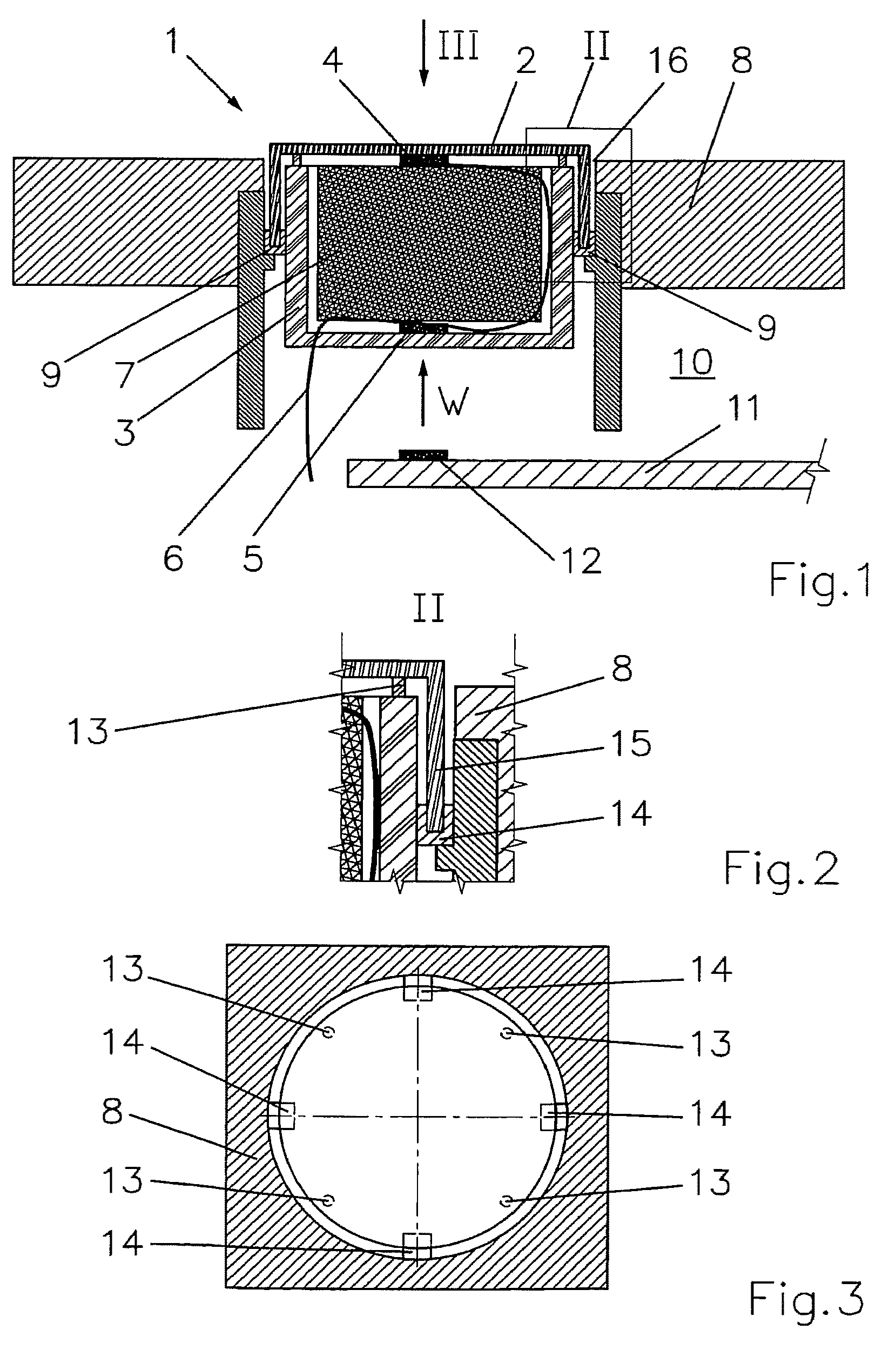
[0017]FIG. 1 shows a sensor arrangement 1 of the invention as a surface sensor 1, a front wall 2, which is part of the housing of surface sensor 1, a rear wall 3, made predominantly of plastic, as the rear section of the housing, a first temperature sensor 4 and a second temperature sensor 5, a flexible line 6, the flexible line 6 being connected to the two temperature sensors 4, 5, and a heat-insulator 7 located in housing 2, 3, which, on the one hand, fills housing 2, 3 and, on the other, acts as insulation between temperature sensors 4, 5. Surface sensor 1 is integrated flush or virtually flush into an aperture 8 of an operating panel of a climate control unit or directly into a dashboard 8. Sensor arrangement 1 is held by means of guide rails 9 in aperture 8. A printed circuit board 11 is shown behind surface sensor 1 in interior 10 of the climate control panel. Another temperature sensor 12 is attached to printed circuit board 11 in this exemplary embodiment.

[0018]Temperature s...


PUM

PropertyMeasurementUnit
distanceaaaaaaaaaa
interior temperatureaaaaaaaaaa
temperatureaaaaaaaaaa

Abstract

A sensor arrangement is provided for determining an interior temperature in a motor vehicle, which sensor arrangement is at least one part of an air-conditioning operating part, comprising a closed housing having at least one front wall and one rear wall, wherein the front wall is manufactured from a material which ensures satisfactory thermal transfer and the housing and is filled with a thermally insulating means, further comprising a first temperature sensor which is fastened to a rear side of the front wall and a second temperature sensor which interacts with the first temperature sensor at least in relation to an evaluation of the interior temperature, wherein the at least second temperature sensor is fastened on an inner side of the rear wall which faces the rear side of the front wall.

Description

[0001]This nonprovisional application is a continuation of International Application No. PCT / EP2007 / 002431, which was filed on Mar. 20, 2007, and which claims priority to German Patent Application Nos. 10 2006 016 821.6, which was filed in Germany on Apr. 7, 2006, and to 10 2007 009 672.2, which was filed in Germany on Feb. 28, 2007 and which are herein incorporated by reference.BACKGROUND OF THE INVENTION[0002]1. Field of the Invention[0003]The invention relates to a sensor arrangement for determining an interior temperature in a motor vehicle, which sensor arrangement is at least one part of a climate control panel, having a closed housing with at least one front wall and a rear wall, whereby the front wall is made of a material assuring good heat transport and the housing is filled with a heat-insulator, a first temperature sensor attached to a back of the front wall, and a second temperature sensor, which works together with the first temperature sensor at least in regard to eva...

Claims


Application Information

Patent Timeline
Patent Type & Authority Patents(United States)
IPC IPC(8): G01K1/14G01K13/00G01K17/06
CPCB60H1/00792G01K1/20G01K2201/02G01K1/16
Inventor REGENSBURGER, JOHANNBAUER, GEORGKRAMLICH, ANDREASREISER, MICHAELKUECHLER, WOLFGANG
Owner PREH GMBH
Learn More