Powerline communication system and method using coupler design for additional users

a technology of powerline communication and coupler design, applied in the field of power line networking techniques, can solve the problems of many limitations still exist, and achieve the effect of selective connection and easy implementation

Inactive Publication Date: 2006-08-10
ASOKA USA CORP
View PDF27 Cites 26 Cited by
  • Summary
  • Abstract
  • Description
  • Claims
  • Application Information

AI Technical Summary

Benefits of technology

[0013] Numerous benefits are achieved using the present invention over conventional techniques. The present invention can be applied using conventional components from computer networking and hardware technologies. Additionally, the invention can be applied to pre-existing powerline structures without substantial modification. Preferably, the present system and method are easy to implement and also selectively connect and depending upon the user. In preferred embodiments, the invention also provides for security between users. Depending upon the embodiment, one or more of these benefits may exist. Additionally, the present system and method can provide for multiple channels of powerline networking capability without pulling additional networking and / or powerlines according to a preferred embodiment. These and other benefits have been described throughout the present specification and more particularly below.

Problems solved by technology

Although powerline communications have been successful in part, many limitations still exist.

Method used


Image

  • Powerline communication system and method using coupler design for additional users
  • Powerline communication system and method using coupler design for additional users
  • Powerline communication system and method using coupler design for additional users

Examples


Embodiment Construction

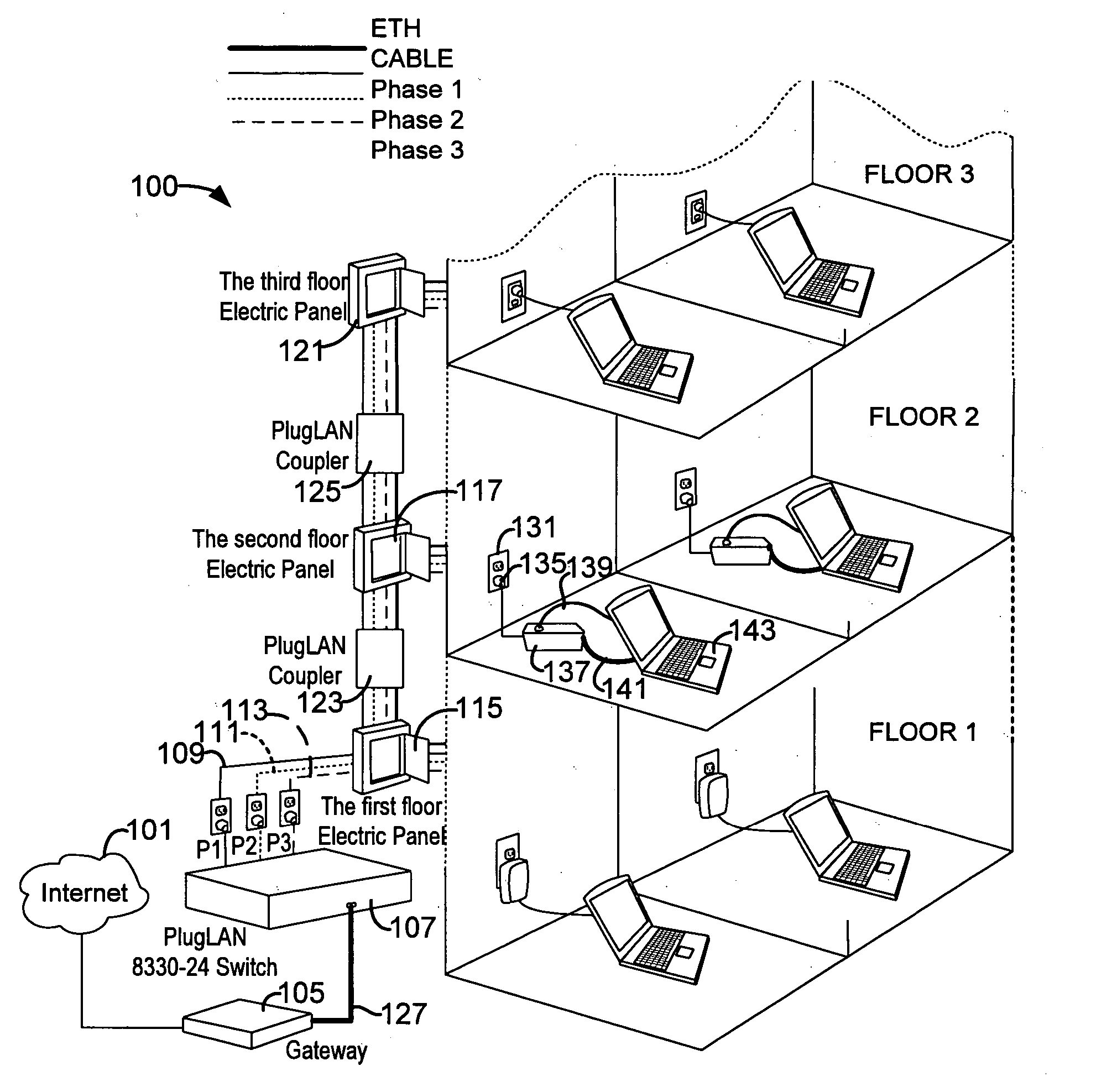
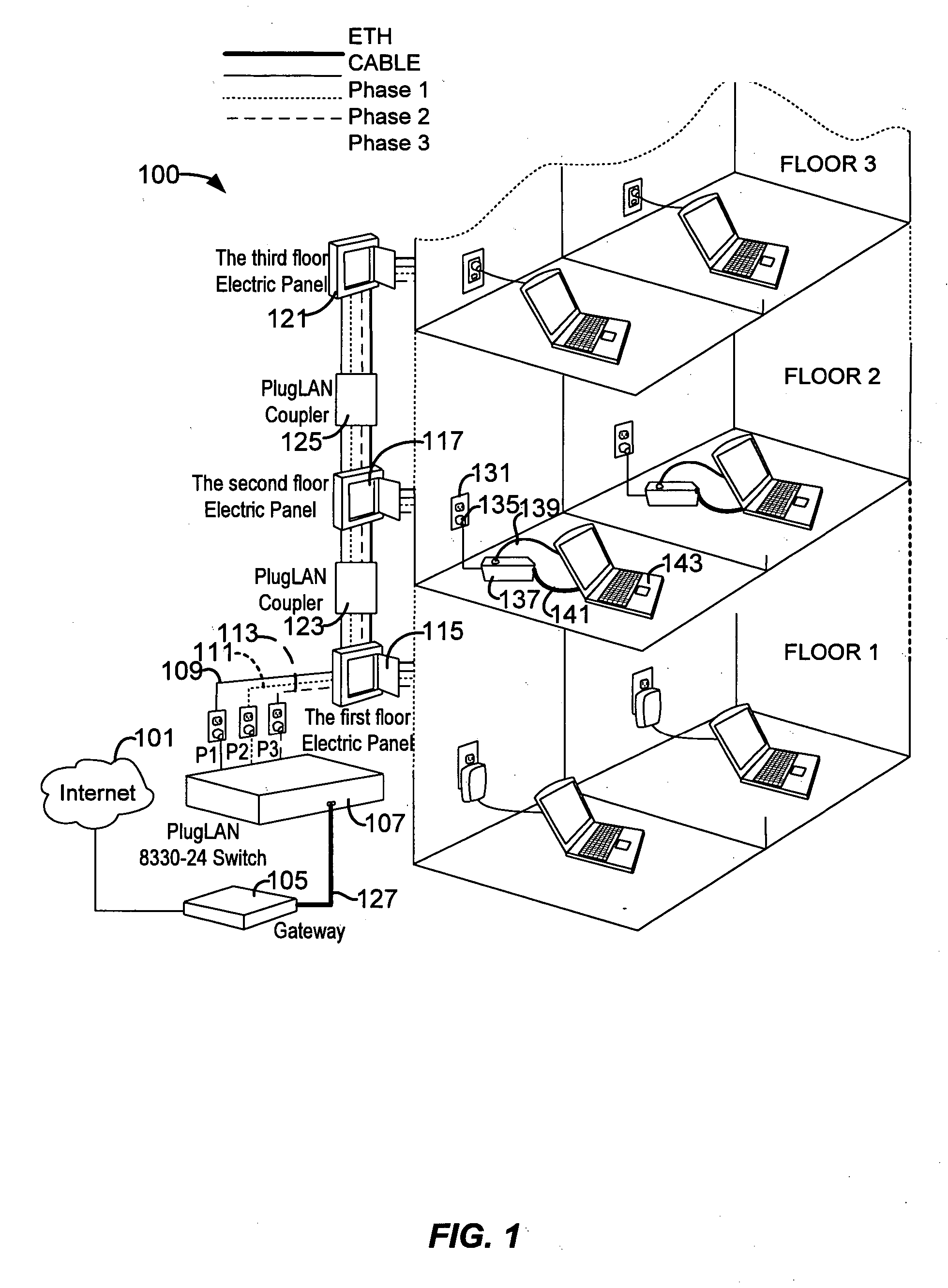
[0022] According to the present invention, techniques for power line networking techniques are provided. More particularly, the invention provides a method and apparatus for installing a multiport powerline networking device onto multiple power supply panels for commercial building applications. Merely by way of example, the invention has been applied to an Ethernet network for building area networking applications, but it would be recognized that other applications exist. The other applications may include any other that may have multiple power supply panels, which feed power into selected regions of use, e.g., apartment, hotel, office, hospital, plant.

[0023]FIG. 1 is a simplified diagram of a powerline system 100 according to an embodiment of the present invention. This diagram is merely an example, which should not unduly limit the scope of the claims herein. One of ordinary skill in the art would recognize many variations, alternatives, and modifications. As shown, the system i...


PUM


Abstract

A powerline network system. The system includes a power transformer device at a public utility facility. The system has a powerline box coupled to the transformer device. In a preferred embodiment, the powerline box comprises at least three lines including a first phase, a second phase, and a third phase. The first phase, the second phase, and the third phase are derived from the power transformer device. The system has a powerline coupler coupled to the first phase, the second phase, and the third phase and a multichannel data communication device coupled to the powerline coupler. In a preferred embodiment, the multichannel data communication device includes N channels, whereupon N is an integer greater than 8. The system has a first capacitor and a second capacitor coupled to the first phase and a first length of wiring between the first capacitor and the second capacitor. Preferably, the first length of wire is inductively coupled to one or more power line communication devices. The system has a third capacitor and a fourth capacitor coupled to the second phase and a second length of wiring between the third capacitor and the fourth capacitor. Preferably, the second length of wiring is inductively coupled to one or more power line communication devices. The system has a fifth capacitor and a sixth capacitor coupled to the third phase and a third length of wiring between the fifth capacitor and the sixth capacitor. Preferably, the third length of wiring is inductively coupled to one or more powerline communication devices.

Description

CROSS-REFERENCES TO RELATED APPLICATIONS [0001] This present application is related to U.S. Ser. No. 10 / 712,748 filed Nov. 11, 2003, which claims priority to U.S. Provisional Application No. 60 / 508,482 filed Oct. 3, 2003, commonly assigned and hereby incorporated for all purposes.BACKGROUND OF THE INVENTION [0002] The present invention relates generally to power line networking techniques. More particularly, the invention provides a method and apparatus for installing a multiport powerline networking device onto multiple power supply panels for commercial building applications or the like. Merely by way of example, the invention has been applied to an Ethernet network for building area networking applications, but it would be recognized that other applications exist. The other applications may include any other that may have multiple power supply panels, which feed power into selected regions of use, e.g., apartment, hotel, office, hospital, plant. [0003] Telecommunication technique...

Claims


Application Information

Patent Timeline
Patent Type & Authority Applications(United States)
IPC IPC(8): H04J15/00H02J3/02H04L27/10G05B11/01G08B1/08H04J99/00
CPCH04B3/54H04B3/542H04B3/544H04B3/56H04B2203/5408H04B2203/5441H04B2203/5445H04B2203/5466H04B2203/5483H04L25/0272H04L27/2601
Inventor CHAN, TAT KEUNGMU, SONGLY
Owner ASOKA USA CORP
Why Eureka
Try Eureka