Paint circulation system

a paint circulation and dispensing system technology, applied in the direction of liquid spraying apparatus, coatings, metal material coating processes, etc., can solve the problems of paint degradation, waste of pumping energy, and high pressur

Inactive Publication Date: 2006-08-10
THE OHIO STATE UNIV RES FOUND
View PDF13 Cites 23 Cited by
  • Summary
  • Abstract
  • Description
  • Claims
  • Application Information

AI Technical Summary

Problems solved by technology

However, all of the other loops (e.g., colors) in the system must remain at elevated pressures in order to maintain paint circulation while not in use.
Such process designs lead to inefficiency, wasted pumping energy and paint degradation, particularly for metallic paints.

Method used


Image

  • Paint circulation system
  • Paint circulation system
  • Paint circulation system

Examples


Embodiment Construction

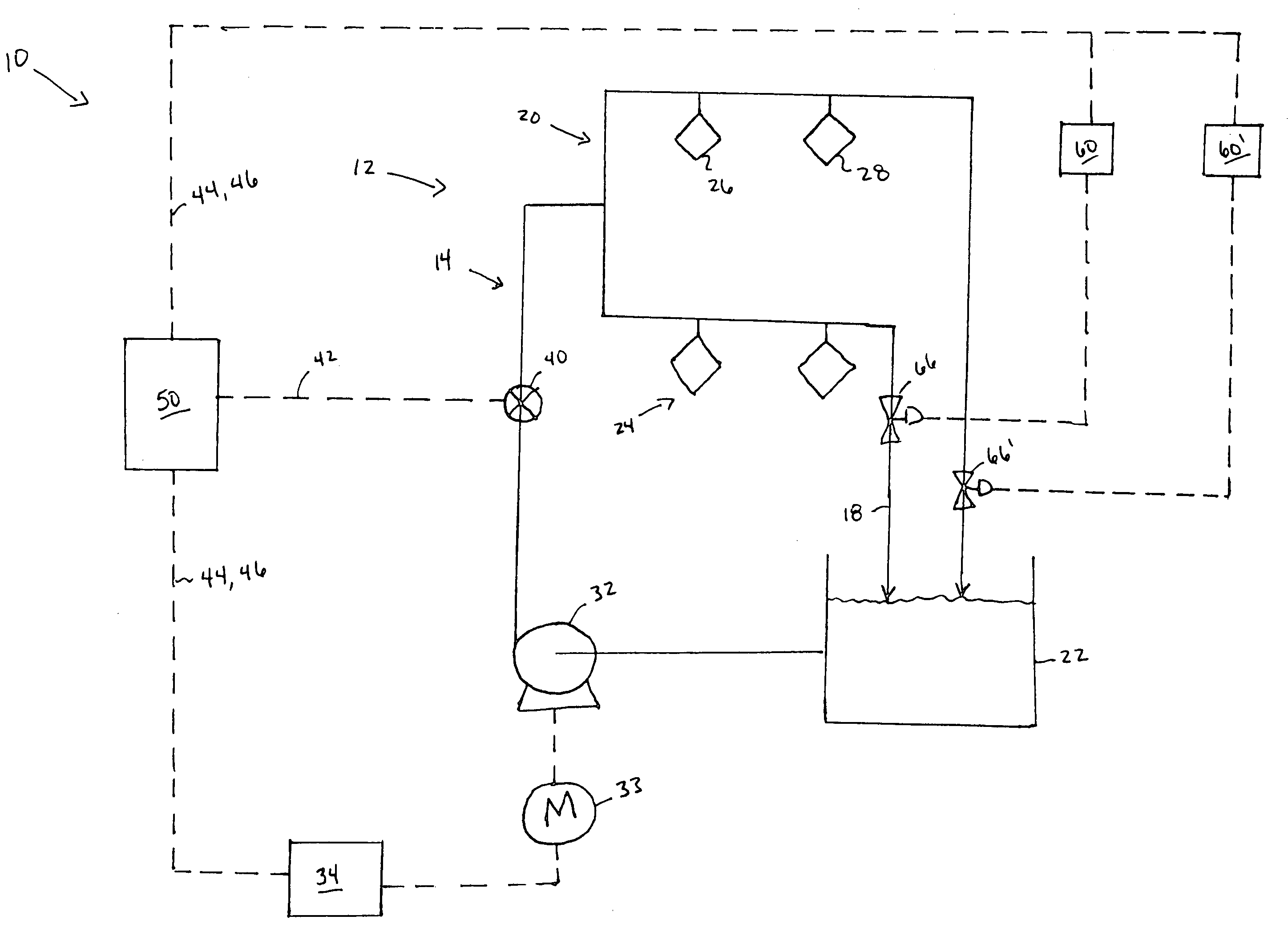
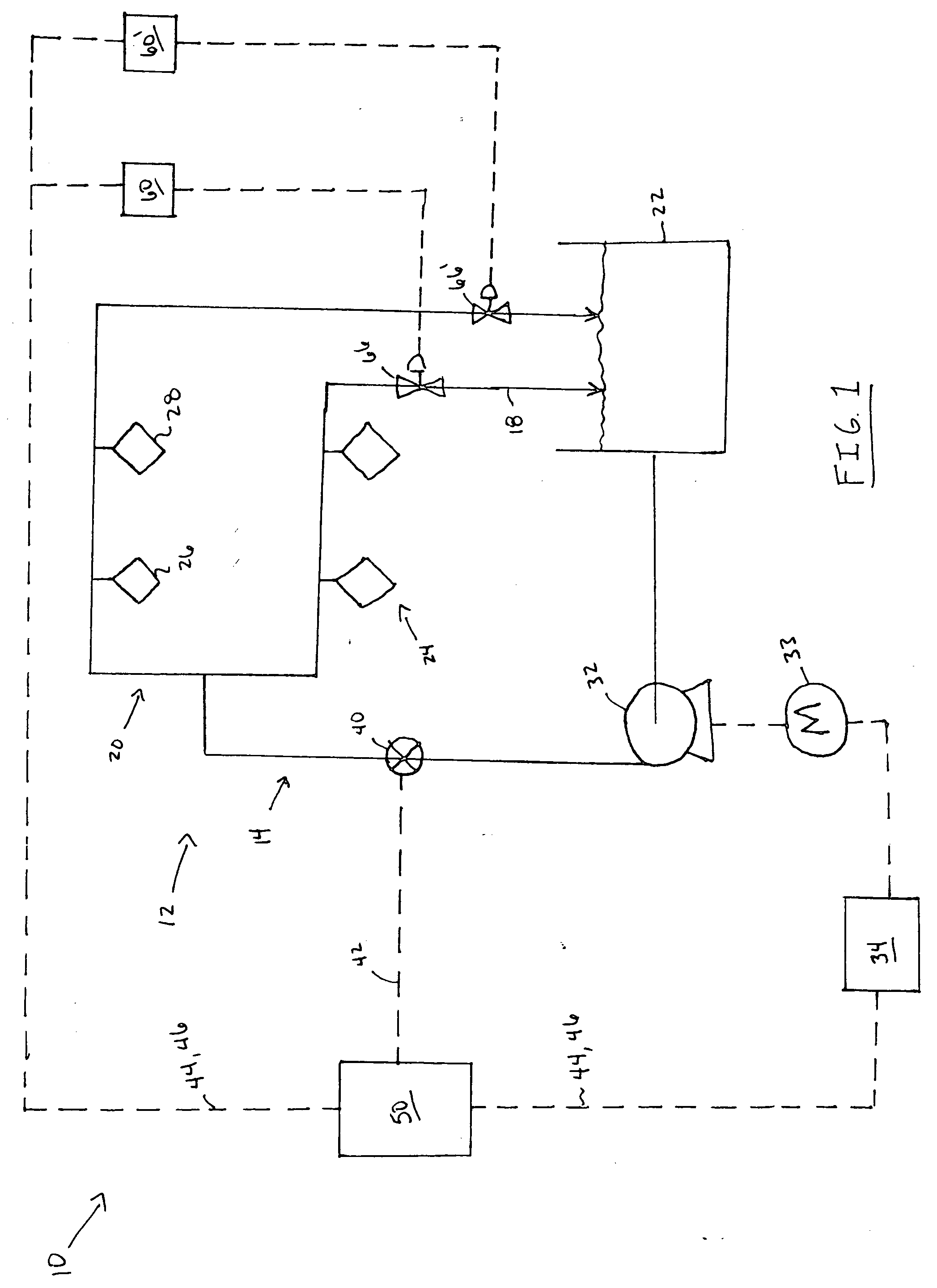
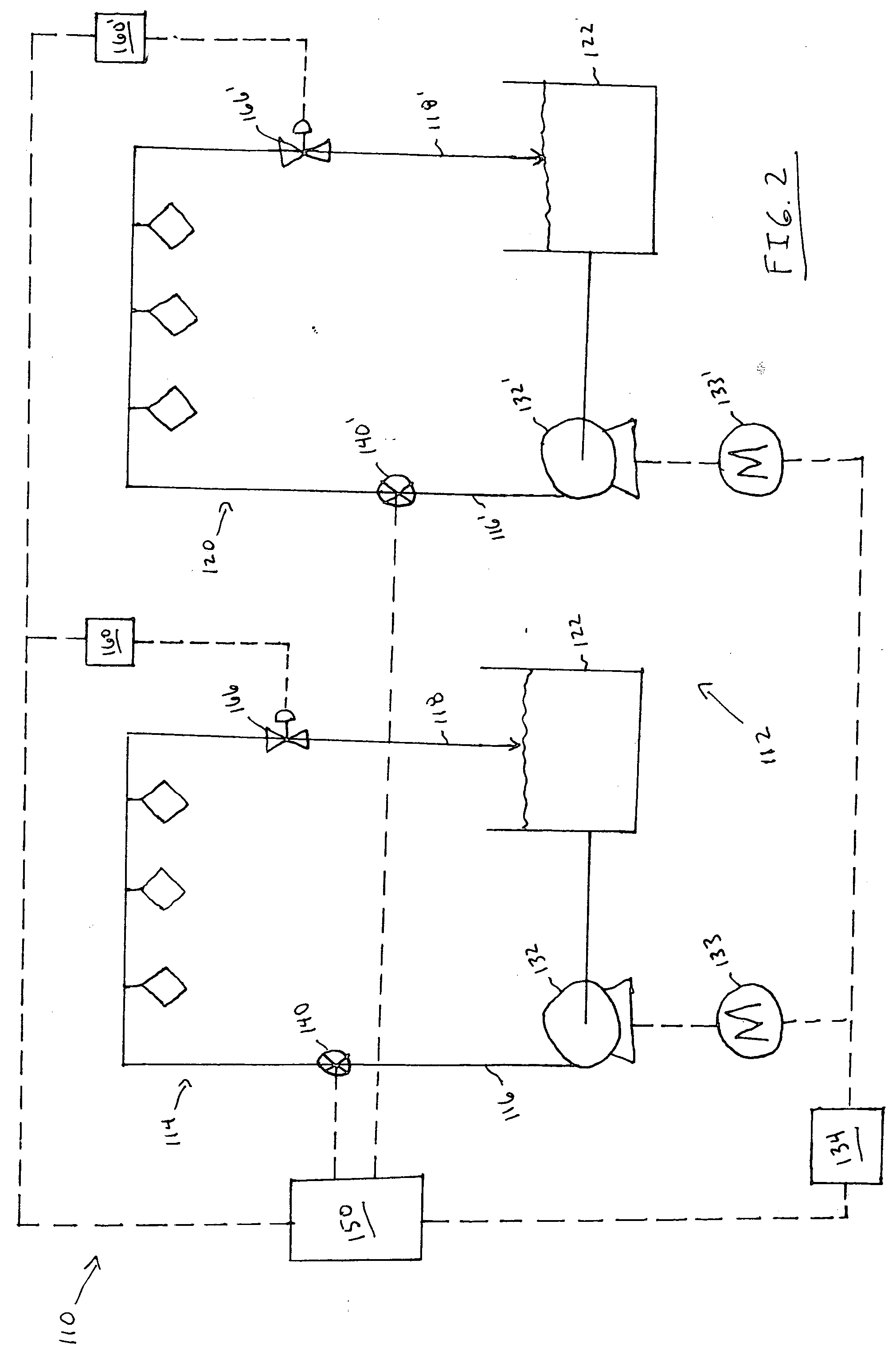
[0012] The present invention provides particular advantages previously unavailable in industries where circulation systems for dispensing paints are applied, particularly in the automotive industry. Current paint circulation system designs require a pressure transmitter to be used downstream of a pump in order to sense pressure fluctuations in the operating loop as spray applicators or distributors are turned on or off. The pressure transmitter sends a signal to the programmable logic controller (PLC) which in turn controls the variable frequency drive (VFD) motor on the pump to change the pump speed and maintain a certain discharge pressure. Moreover, under such systems it is known that some paints do not remain stable with respect to some of their property characteristics, over time, particularly when they are subjected to shear forces while being pumped throughout the circulation system.

[0013] In contrast to prior systems, the present invention provides a paint circulation syste...


PUM

PropertyMeasurementUnit
pressureaaaaaaaaaa
metallicaaaaaaaaaa
viscosityaaaaaaaaaa

Abstract

Circulation systems and methods for dispensing paint, more particularly those systems and methods which are configured to provide one or more paints to automotive paint applications are provided.

Description

TECHNICAL FIELD [0001] The present invention relates to a paint circulation and dispensing system and method, and more particularly to a closed loop system and method capable of providing one or more paints for automotive paint applications. BACKGROUND OF THE INVENTION [0002] Sophisticated painting systems are commonly used in automotive manufacturing facilities to provide the final paint finish on vehicles. Conventional large painting systems generally include several paint booths each equipped with multiple paint loops, with each loop consisting of one color. A paint loop generally includes a tank, a pump, piping, and multiple paint distributors (e.g., spray guns or robots). In order to provide the necessary pressure for the paint distributors to properly operate and to avoid particles in the paint from settling, the pump is continuously operated. [0003] Current paint system designs are generally operated as batch processes, where only one color is applied to a vehicle at one time...

Claims


Application Information

Patent Timeline
Patent Type & Authority Applications(United States)
IPC IPC(8): C23C16/52B05C11/00
CPCB05B9/0406B05B9/0423B05B12/085B05B12/10
Inventor BHATTACHARYA, SHUBHOXU, JIANHUAKOELLING, KURT W.
Owner THE OHIO STATE UNIV RES FOUND
Why Eureka
Try Eureka