Automotive paint spray and drying booth

a technology for automotives and paint spraying, which is applied in the direction of drying machines, drying machines with materials at rest, light and heating apparatus, etc. it can solve the problems of unduly prolonging the drying time of paint applied to the vehicle, reducing the overall temperature of the air, and affecting the drying effect of pain

Active Publication Date: 2014-09-09
DEDOES IND LLC
View PDF10 Cites 8 Cited by
  • Summary
  • Abstract
  • Description
  • Claims
  • Application Information

AI Technical Summary

Benefits of technology

[0013]Other alternative ways such as using shop compressed air to create the air flow within the paint spray and drying booth, the air output from the regenerative blower provides low humid air from the heat it produces. As such, it facilitates the drying of paint and particularly the drying of water based paints.

Problems solved by technology

One disadvantage of utilizing the shop compressed air as the air flow source for the paint spray and drying booth is that such compressed air contains a relatively highly portion of moisture.
While such moisture was acceptable, or at least tolerated, for the previously used solvent based paints, with the newer water based automotive paints and finishes, the humid air from the shop compressed air supply unduly prolongs the drying time for the paint applied to the vehicle.
A still further disadvantage of using shop compressed air to create the air flow in the drying booth is that the release of the pressurized shop air through the air nozzles reduces the overall temperature of the air.
However, the use of external heaters to heat the compressed air results in increased energy consumption and, accordingly, increased operational cost.

Method used


Image

  • Automotive paint spray and drying booth
  • Automotive paint spray and drying booth
  • Automotive paint spray and drying booth

Examples


Embodiment Construction

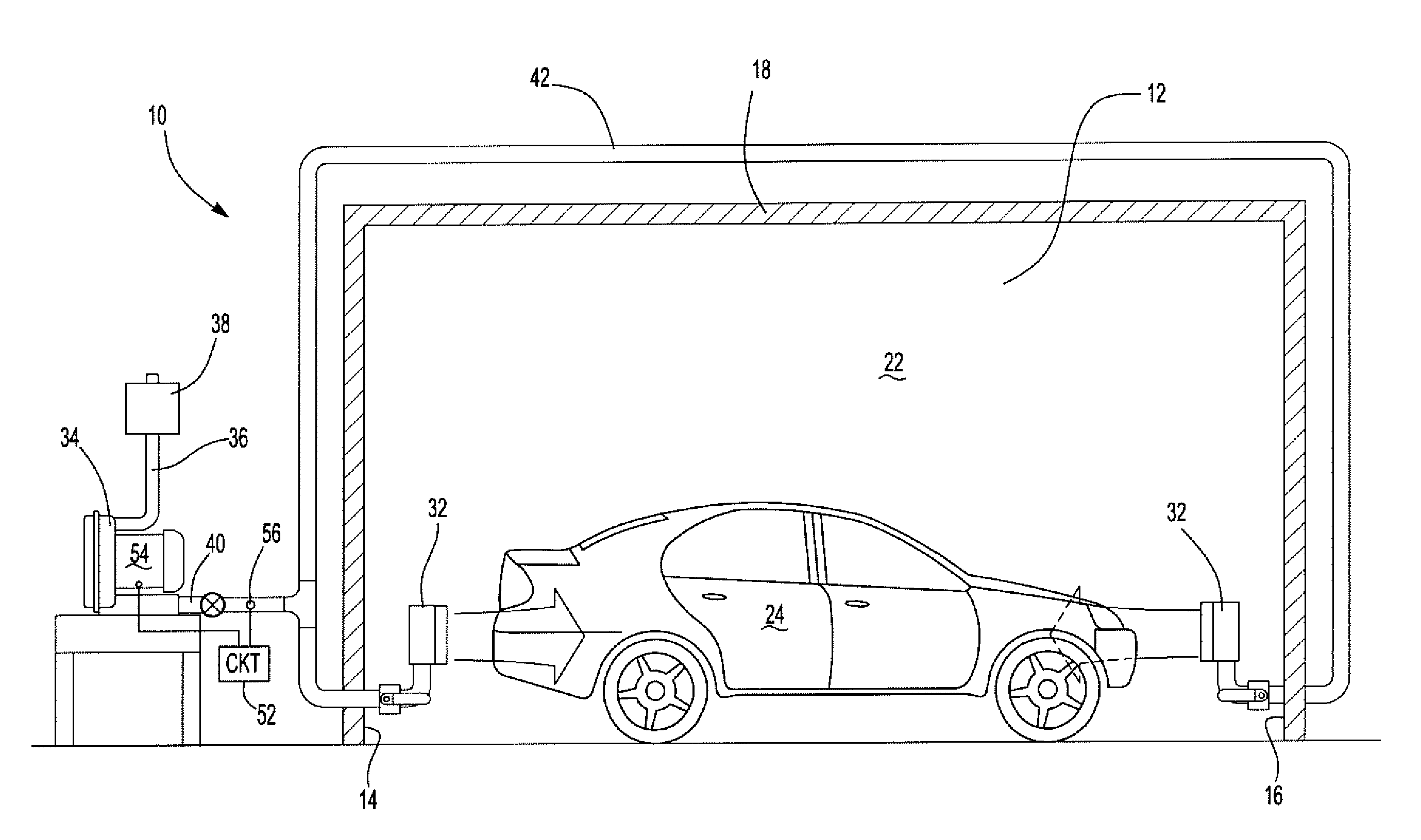
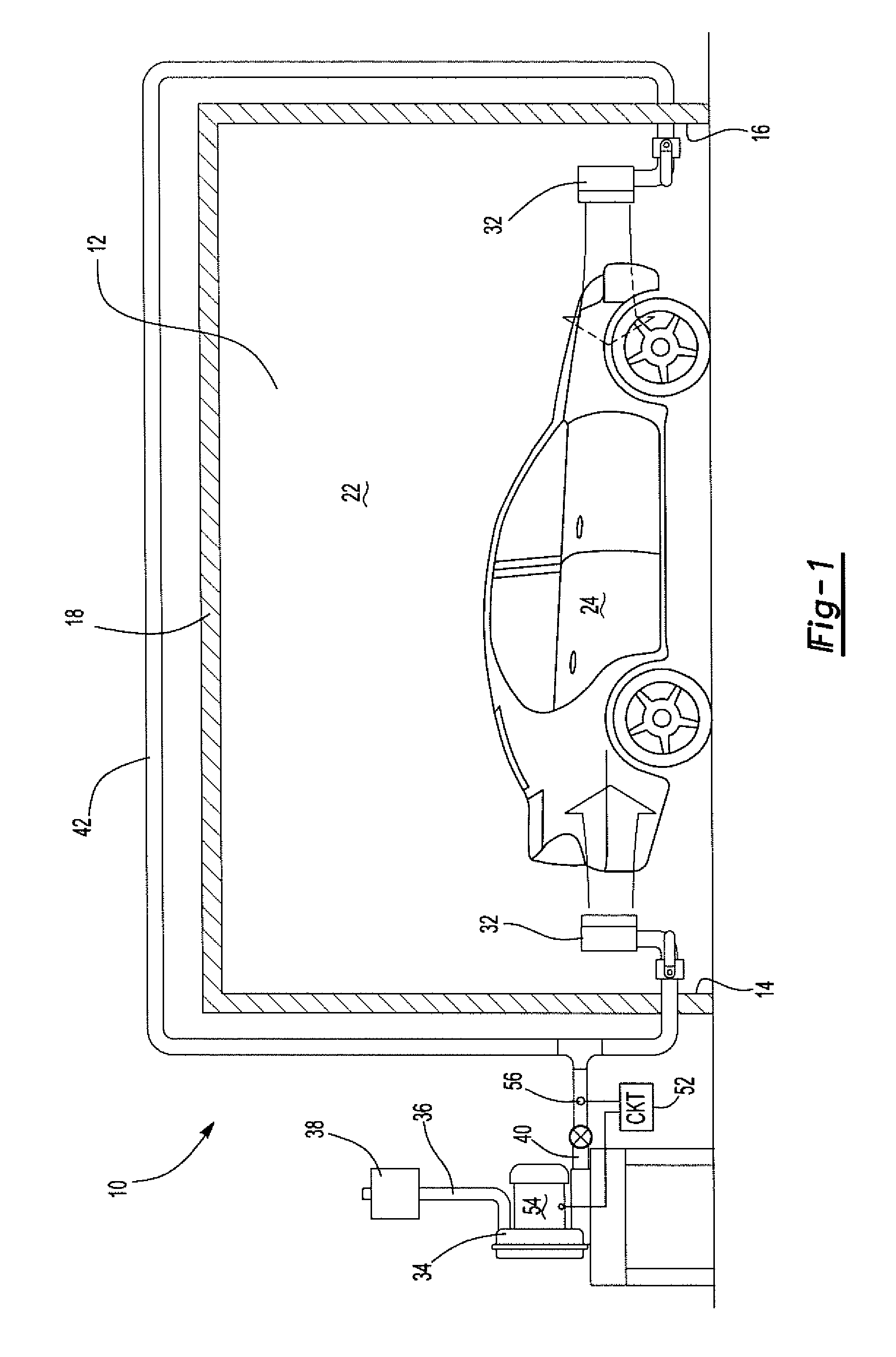
[0020]With reference first to FIGS. 1 and 2, a preferred embodiment of a paint spray and drying booth 10 in accordance with the present invention is shown. The booth includes a pair of spaced apart side walls 12 (only one shown), two end walls 14 and 16, as well as a top wall 18 and floor 20. Together, the side walls 12, end walls 14 and 16, top wall 18, and floor 20 form a chamber 22 which is of a size sufficient to receive an automotive vehicle 24.

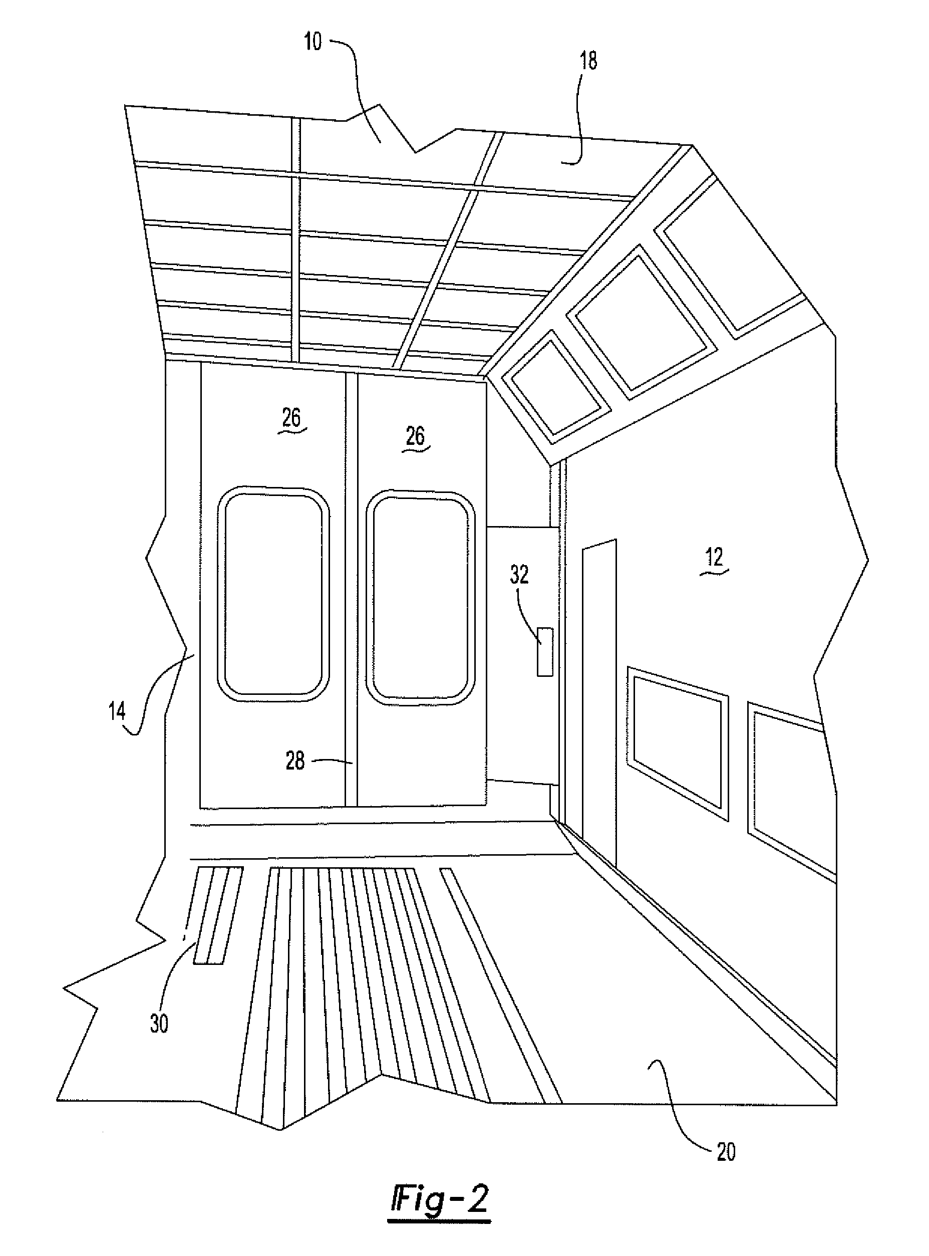
[0021]As best shown in FIG. 2, at least one end wall 14 includes access doors 26 to provide access into and out of the interior chamber 22 for the automotive vehicle 24. Preferably, the doors 26 include seals 28 around an outer periphery to minimize the leakage of air around the doors and into the chamber 22.

[0022]Still referring to FIG. 2, the floor 20 preferably includes at least one grate 30 which is fluidly connected to an air exhaust. Consequently, air flow into the interior chamber 22 of the booth 10 will eventually flow out throug...


PUM


Abstract

An automotive paint spray and drying booth having a plurality of walls which, together, define a housing with a chamber sufficient in size to contain an automotive vehicle. An air dispenser is positioned within the chamber and the air dispenser includes an outlet positioned to direct air along one or more of the housing walls. A regenerative blower is positioned outside the housing chamber. The blower is connected to an inlet open outside of the housing chamber and includes an outlet which is fluidly connected to the air nozzle.

Description

BACKGROUND OF THE INVENTION[0001]I. Field of the Invention[0002]The present invention relates generally to drying automotive coatings in paint booths and preparation decks for automotive vehicles.[0003]II. Description of Related Art[0004]Many automotive repair shops, oftentimes called collision shops, maintain an automotive paint spray and drying booth. These booths include a plurality of walls which, together, define a chamber of size sufficient to contain an automotive vehicle.[0005]One or more air dispensers are positioned within the interior chamber of the drying booth housing. These air dispensers are typically connected to the shop supply of pressurized air. Consequently, when the pressurized air is connected fluidly to the nozzle, air flow occurs around the automotive vehicle which not only removes paint particles from the booth, but also serves to dry the paint after application on the vehicle.[0006]One disadvantage of utilizing the shop compressed air as the air flow source...

Claims


Application Information

Patent Timeline
Patent Type & Authority Patents(United States)
IPC IPC(8): F26B11/02
CPCF26B21/12F26B9/06F26B2210/12
Inventor HAHN, PAULHAHN, RICHARD J.
Owner DEDOES IND LLC
Why Eureka
Try Eureka