
Breech loaded fixed needle syringe and automatic injection device having the same

a technology of automatic injection and fixed needle syringe, which is applied in the direction of automatic syringe, ampoule syringe, intravenous device, etc., can solve the problems of increasing the damage to tissue at the injection site, more pain inflicted on the person receiving the injection, and the gauge of the needle for a syringe filled at the time of use is, typically, limited by the strength of the column, and the needle is long and thin

Inactive Publication Date: 2006-08-10
WEST PHARMA SERVICES OF DELAWARE
View PDF99 Cites 64 Cited by
  • Summary
  • Abstract
  • Description
  • Claims
  • Application Information

AI Technical Summary

Benefits of technology

[0013] It is another object to provide a fixed needle syringe that can be loaded with fluid medicament without the need to aspirate the medicament through the same needle that is later used to penetrate the tissue and provide a conduit for flow into the injection site.
[0014] It is another object to provide a fixed needle syringe that removes the size limitations on the hypodermic needle associated with the dual use of the hypodermic needle of the prior art, i.e. the prior art's requirement for the same needle to be used as a conduit from the original medicine vial into the fixed needle syringe and also from the fixed needle syringe into the recipient of the injection.

Problems solved by technology

Unfortunately, the larger the needle gauge, the greater the damage to tissue at the injection site and more pain inflicted upon the person receiving the injection.
The gauge of the needle for a syringe filled at the time of use is, typically, limited by the column strength of the needle when inserting and withdrawing the needle from the medicine vial.
Long, thin needles are more prone to fail in buckling while attempting to puncture the septum of the medicine vial.
Further, the gauge is a limiting factor in aspirating drug solutions from another container, as the flow of fluid from the medicine vial into the syringe is determined, in part, by the inner diameter and length of the needle, the viscosity of the drug solution, and the differential pressure available to cause fluid flow; the maximum pressure during aspiration being atmospheric pressure.

Method used


Image

  • Breech loaded fixed needle syringe and automatic injection device having the same
  • Breech loaded fixed needle syringe and automatic injection device having the same
  • Breech loaded fixed needle syringe and automatic injection device having the same

Examples


Embodiment Construction

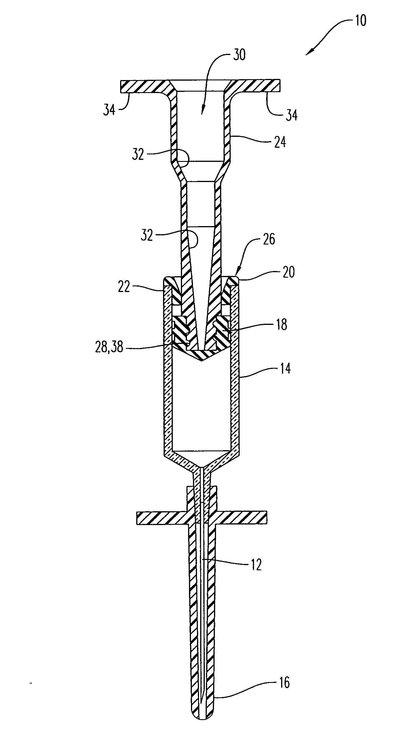
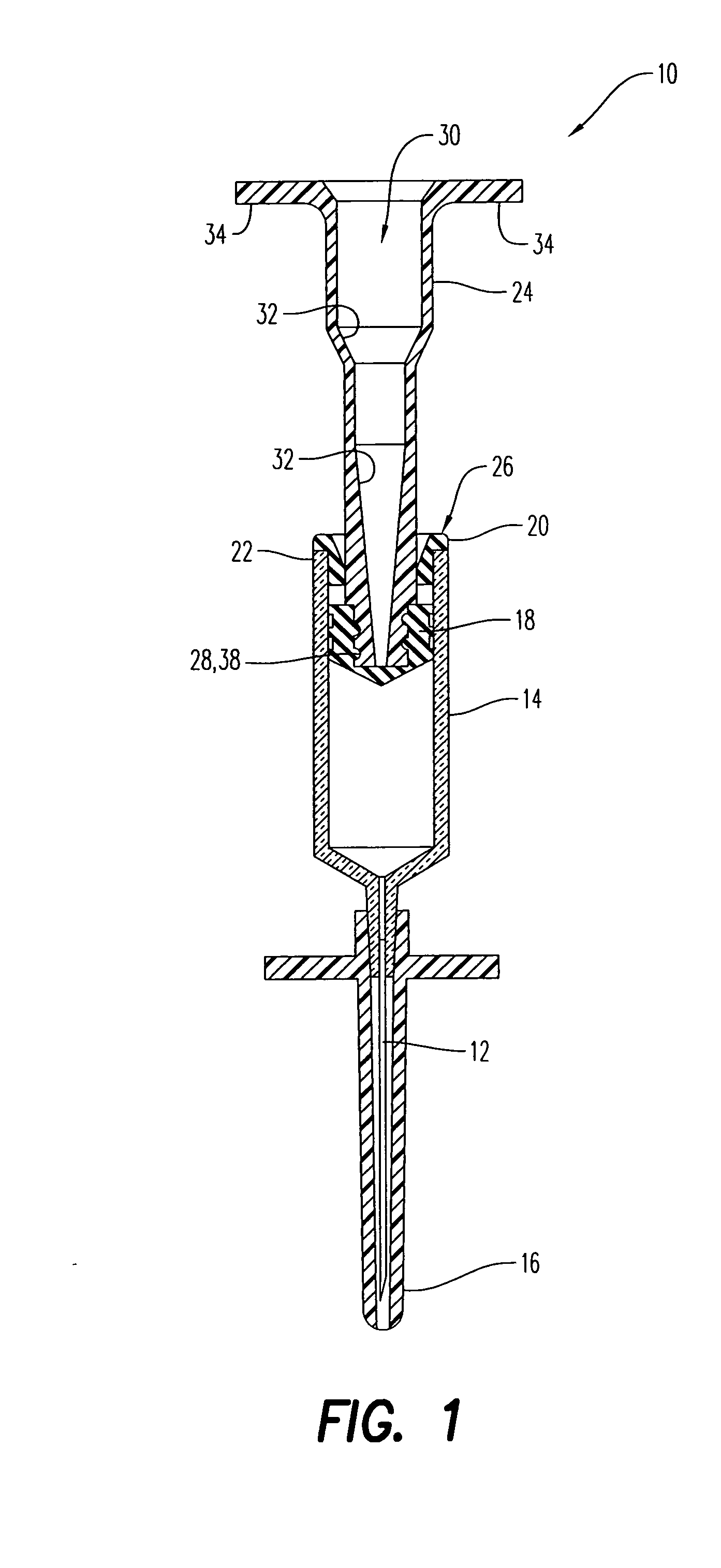
[0025] Referring to the figures and in particular to FIG. 1, an exemplary embodiment of a fixed needle syringe 10 according to the present disclosure is shown. Syringe 10 includes a hypodermic needle 12 in fluid communication with a medicine compartment 14. In some embodiments, syringe 10 can include a removable protective cover 16 disposed over hypodermic needle 12.

[0026] Syringe 10 also includes a piston 18 slideably disposed in medicine compartment 14. Preferably, syringe 10 includes a syringe end cap 20 at a breech end 22 of medicine compartment 14 to prevent inadvertent withdrawal of piston 18 from the medicine compartment.

[0027] Advantageously, syringe 10 is configured so that compartment 14 can be filled with medicine through piston 18.

[0028] It has been determined by the present disclosure that the size of the hypodermic needle is limited by the forces imposed on hypodermic needle 12 during aspiration. Advantageously, syringe 10 disassociates the forces imposed on hypoder...


PUM


Abstract

A fixed needle syringe having a medicine compartment, a hypodermic needle, a piston, and a plunger is provided. The hypodermic needle is in fluid communication with the medicine compartment. The piston is slideably disposed in the medicine compartment. The plunger is secured to the piston. The plunger has a bore defined therethrough, where the bore allows access to the piston through the plunger.

Description

CROSS REFERENCE TO RELATED APPLICATIONS [0001] This application claims priority of U.S. Provisional Application Ser. No. 60 / 634,486 filed on Dec. 9, 2004 and is related to commonly owned and assigned U.S. application Ser. No. 10 / 601,212, filed Jun. 20, 2003, the contents of both of which are incorporated by reference herein.BACKGROUND OF THE INVENTION [0002] 1. Field of the Invention [0003] The present disclosure is related to fixed needle syringes. More particularly, the present disclosure is related to breech loaded fixed needle syringes and automatic injection devices having the same. [0004] 2. Description of Related Art [0005] Fixed needle syringes typically include a needle fixed to and in fluid communication with a medicine compartment. A plunger, often acting on an elastomeric piston in the medicine compartment, is used fill the medicine compartment by drawing-in or aspirating (hereinafter “aspirating”) drug solutions from another container such as a medicine vial or ampoule,...

Claims


Application Information

Patent Timeline
IPC IPC(8): A61M5/315
CPCA61M5/001A61M5/1782A61M5/2033A61M5/2459A61M5/286A61M5/3129A61M2005/31516A61M5/3202A61M5/326A61M2005/206A61M2005/2073A61M2005/2403A61M2005/3107A61M5/31596
Inventor GILLESPIE, RICHARD DAVIDCROW, DOUG OWEN
Owner WEST PHARMA SERVICES OF DELAWARE
Learn More