Automatic suction and repelling device for rivet gun

a technology of automatic suction and rivet gun, which is applied in the field of rivet gun, can solve the problems of not working synchronously with the pull rod assembly, the rivet gun cannot be correctly plugged in the round hole or in a sloping position,

Inactive Publication Date: 2006-08-17
LIN YU CHING
View PDF0 Cites 5 Cited by
  • Summary
  • Abstract
  • Description
  • Claims
  • Application Information

AI Technical Summary

Problems solved by technology

According to the aforesaid rivet gun, the pull rod of a rivet has to be plugged into a round hole on front end of the pull rod assembly, and then the rivet is plugged into a rivet hole before a rivet-pulling work being started; finally pull the trigger to start the rivet-pulling work; however, the conventional rivet gun is not furnished with a nail-sucking device between the pull rod hole and the round hole of the pull rod assembly; as a result, a rivet can not be plugged in the round hole correctly or in a sloping position before the rivet-pulling working being done.
The aforesaid rivet gun has a nail-sucking function all right, but it must have an outer tube to connect with an outer control valve, and it can not work synchronously with the pull rod assembly.

Method used


Image

  • Automatic suction and repelling device for rivet gun
  • Automatic suction and repelling device for rivet gun
  • Automatic suction and repelling device for rivet gun

Examples


Embodiment Construction

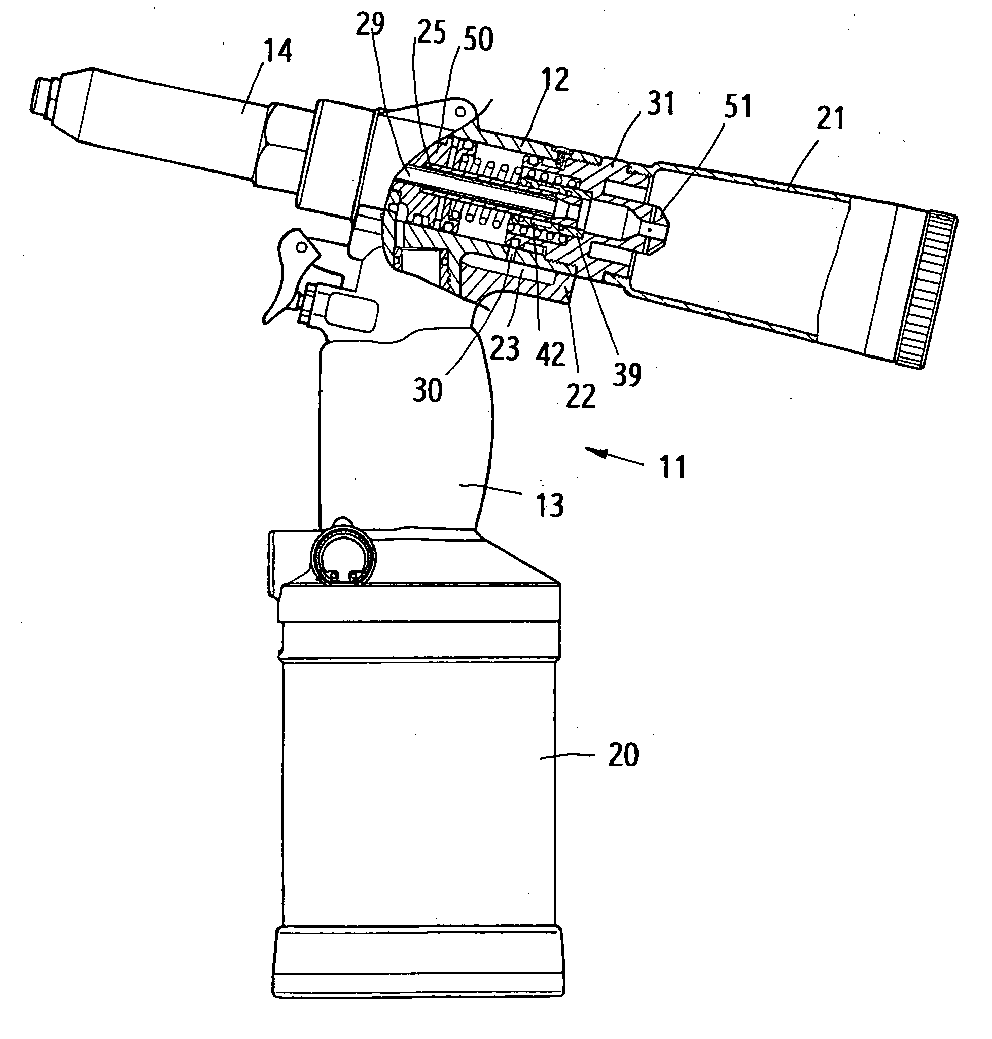
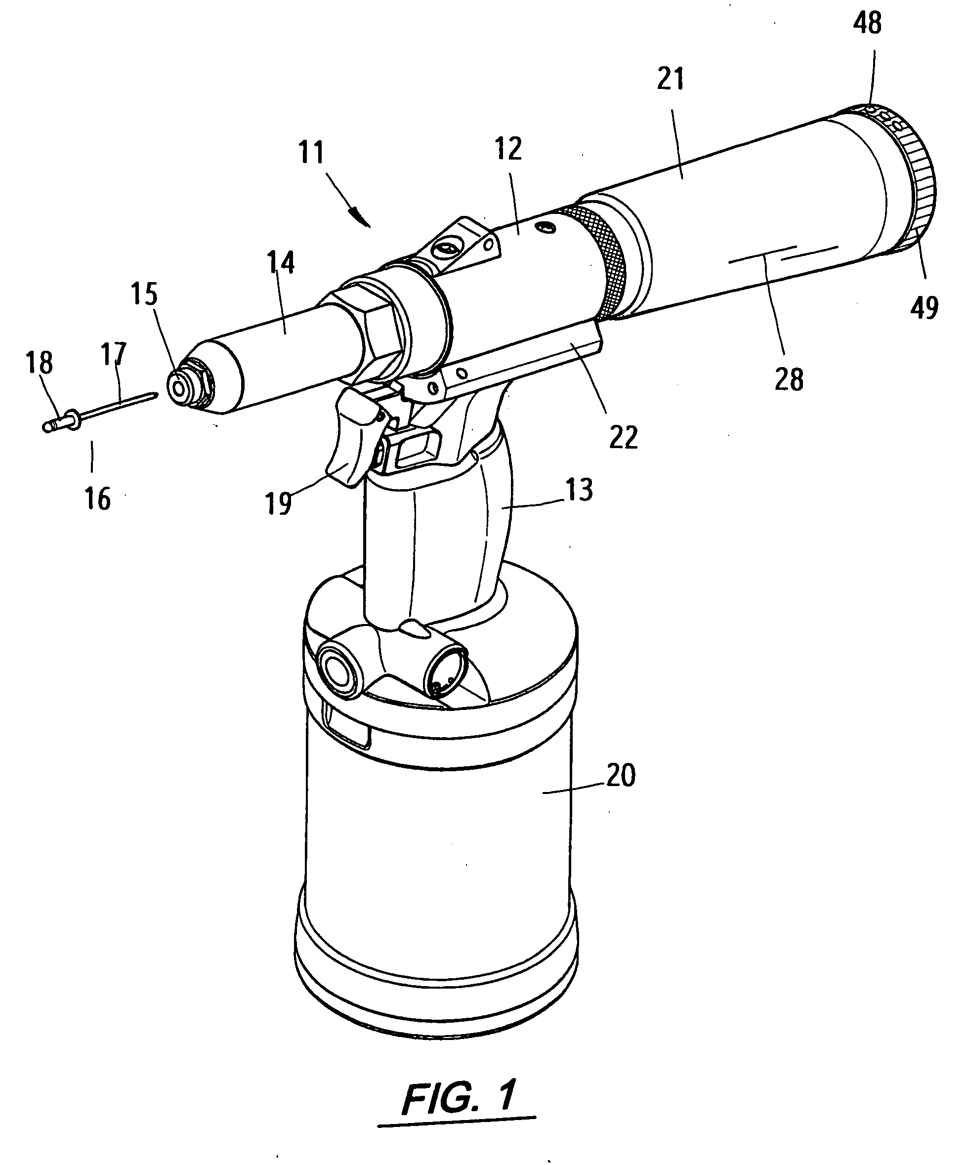
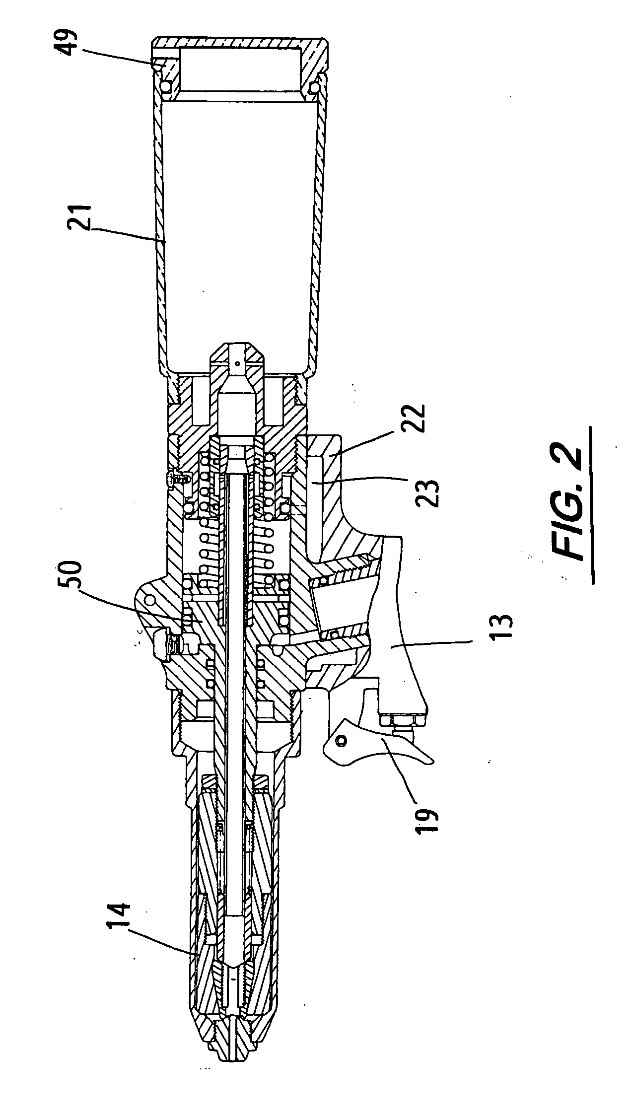
[0017] This invention relates to an automatic suction and repellent device for rivet gun; as shown in FIG. 1, the rivet gun 11 comprises a handle 13 with a pressure-air tank 20 under the handle, a trigger 19; a support frame 22, and a body 12 above the handle. The front end of the body 12 is furnished with a pull rod assembly 14, while the rear end thereof is furnished with a used-rivet cylinder 21. During rivet-pulling work, the used-nail cylinder 21 and the body 12 will be adjusted to a given space so as to have the intake passage 23 in the support frame 22 and the center passage in the body 12 aligned into a backward repelling passage, and to have a round hole on front end of the pull rod assembly 14 had a vacuum suction force; after the rivet pin 16 and the pull rod assembly 14 are assembled together, it would provide the functions of sucking, positioning and preventing from dropping so as to complete the rivet-pulling work; then, the used nail 28 can be sucked by means of vacuu...


PUM

PropertyMeasurementUnit
pressureaaaaaaaaaa
volumeaaaaaaaaaa
return forceaaaaaaaaaa

Abstract

An automatic suction and repelling device for rivet gun, which comprises a body and a handle, and the intake passages thereof are in communication each other; the rear center of the body is furnished with a regulation ring and a used-nail cylinder; the regulation ring can be adjusted to move by means of screwing so as to adjust the volume of pressure air to enter the body, and to adjust the vacuum suction force in the used-nail pipe; during rivet-pulling work, the rivet gun can automatically suck in, and can suck a used nail into the used-nail cylinder upon the rivet-pulling work done.

Description

BACKGROUND OF THE INVENTION [0001] 1. Field of the Invention [0002] This invention relates to a rivet gun, and particularly to an automatic suction and repelling device for a rivet gun. [0003] 2. Description of the Prior Art [0004] In a conventional rivet gun, a pressure-air tank is furnished under the handle; upon a pressure air entering the pressure-air tank, it can drive a piston to move; the pressure air is then changed into a hydraulic pressure so as to enable a pulling device to pull a pull rod assembly on the front end thereof, and to provide a rivet-pulling force. [0005] According to the aforesaid rivet gun, the pull rod of a rivet has to be plugged into a round hole on front end of the pull rod assembly, and then the rivet is plugged into a rivet hole before a rivet-pulling work being started; finally pull the trigger to start the rivet-pulling work; however, the conventional rivet gun is not furnished with a nail-sucking device between the pull rod hole and the round hole ...

Claims


Application Information

Patent Timeline
Patent Type & Authority Applications(United States)
IPC IPC(8): B23P11/00
CPCB21J15/043B21J15/105B21J15/326Y10T29/53743Y10T29/53748Y10T29/5373Y10T29/53739
Inventor LIN, YU-CHING
Owner LIN YU CHING
Why Eureka
Try Eureka