Heating and drawing apparatus and method of manufacturing glass spacer using the same

a technology of drawing apparatus and glass spacer, which is applied in the manufacture of electrode systems, manufacturing tools, and manufacturing of electric discharge tubes/lamps, etc., can solve the problems of low stability and assembly efficiency of panels, distortion of displayed images, and hardly obtained support strength, etc., and achieve the effect of suppressing charging

Inactive Publication Date: 2006-08-17
CANON KK
View PDF5 Cites 6 Cited by
  • Summary
  • Abstract
  • Description
  • Claims
  • Application Information

AI Technical Summary

Benefits of technology

[0011] It is an object of the present invention to manufacture a highly-controllable spacer which solves the above problems and has grooves on a surface thereof in order to suppress charging, as designed.

Problems solved by technology

When the spacer is charged, the orbit of electrons emitted from the electron-emitting devices cannot be controlled precisely, thereby causing a problem such as a distortion of a displayed image.
When the spacer having this shape is installed upright so as to be horizontally long on a substrate (the drawing direction is parallel to the substrate), as the contact surface of the spacer with the substrate is curved, the stability and the assembly efficiency of the panel lower and support strength is hardly obtained.
When the spacer having this shape is used, as the inside pressure of the panel is reduced, required atmospheric pressure-resistant supportability may not be obtained.
Further, when the controllability of the sectional form of the spacer is low, in the case of a spacer having grooves which are formed on the surface in order to suppress charging, designed grooves are not obtained, thereby making it impossible to obtain a desired charging suppression effect.

Method used


Image

  • Heating and drawing apparatus and method of manufacturing glass spacer using the same
  • Heating and drawing apparatus and method of manufacturing glass spacer using the same
  • Heating and drawing apparatus and method of manufacturing glass spacer using the same

Examples


example 1

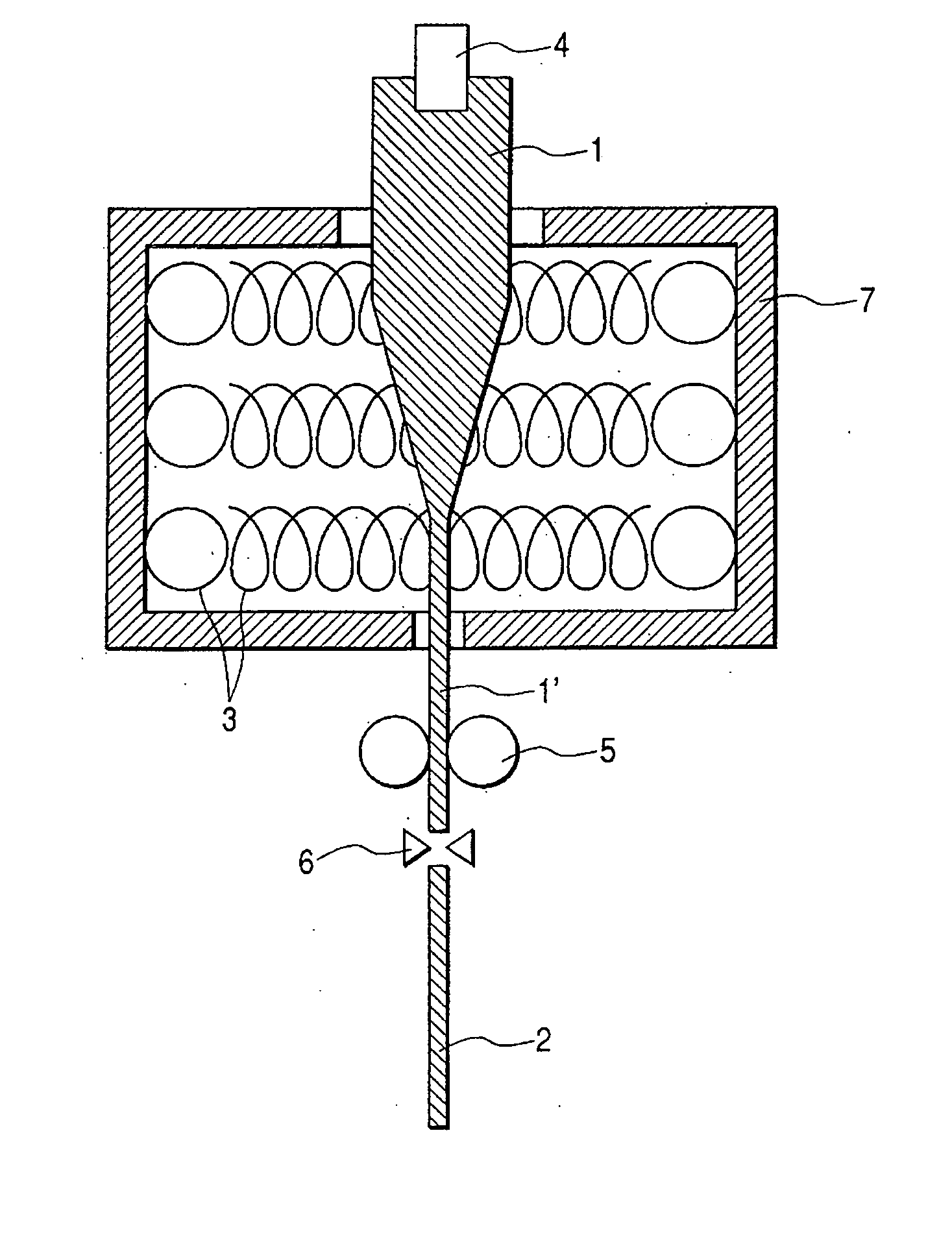
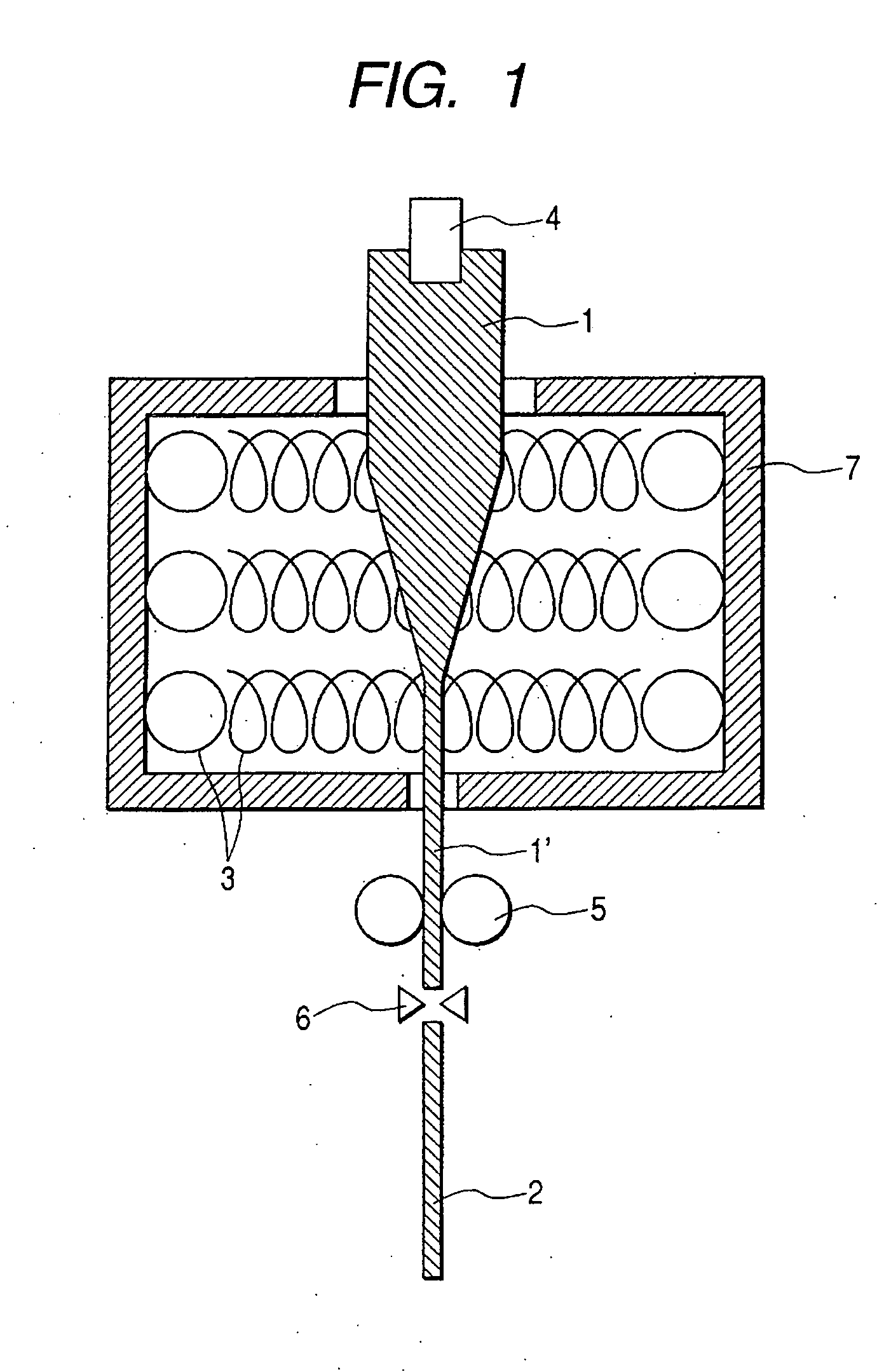
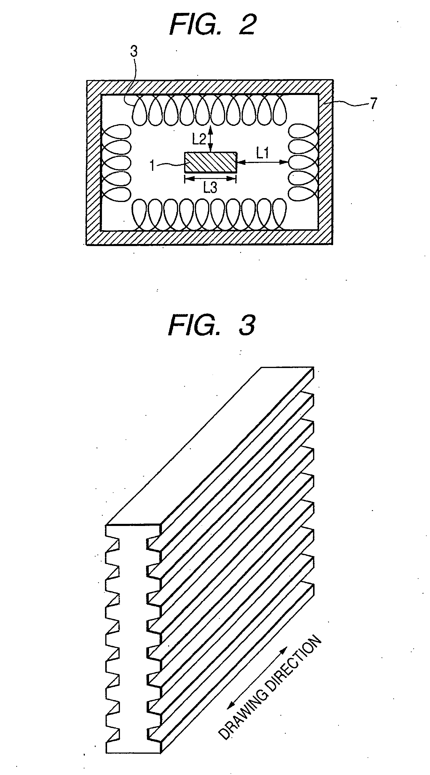
[0036] A glass base material having an oblong-rectangular section measuring 6.15 mm×49.23 mm and 40 trapezoidal grooves with a depth of 0.335 mm and a pitch of 0.923 mm on the surface was used. The heating and drawing apparatus shown in FIG. 1 was used. A heater 3 opposed to the longitudinal direction (49.23 mm) of the above section had a length of 130 mm, and a heater 3 opposed to the transverse direction (6.15 mm) of the section had a length of 86 mm. These heaters were each arranged at positions about 49 mm away from the surfaces of the glass base material. The centers in the longitudinal direction of the heaters 3 were aligned with each other in each direction. In other word, the base material is positioned with respect to the heaters in such a manner that the center of each side of the base material is aligned with the center of the side of the heater opposed to the side of the base material.

[0037]FIG. 8 shows the heat flux output of a 130 mm-long heater 3 which has heated the...

example 2

[0041] The same heating and drawing apparatus as that of Example 1 was used to manufacture a spacer 2 in the same manner as in Example 1 except that the viscosity of the glass base material was set to 107.6 P and 107.9 P by reducing the drawing temperature. As a result, a high-quality spacer was obtained as in Example 1 when drawing was carried out at these viscosities.

example 3

[0043] The same heating and drawing apparatus as that of Example 1 was used to manufacture a spacer 2 in the same manner as in Example 1 except that the viscosity of the glass base material was set to 107.1 P and 107.3 P by increasing the drawing temperature. Although the temperature of the glass base material could be made uniform at high accuracy in Example 3 as well, the drawing temperature was raised by increasing the temperatures of the heaters, thereby reducing the viscosity of the glass base material. This resulted in a variation in the depths of the grooves of about 3% for respective viscosities. However, the distortion of an image was not observed on a display employing this spacer, and high image quality could be obtained.

[0044] Examples of the present invention have been described above. In the above-described examples, the heater and the base material are arranged such that the center of the heater and the center of the base material are aligned with each other. The pre...


PUM

PropertyMeasurementUnit
viscosityaaaaaaaaaa
viscosityaaaaaaaaaa
viscosityaaaaaaaaaa

Abstract

A glass spacer having no swell at the end portions and no constriction at the middle portion and designed grooves is manufactured by a heating and drawing method. The heat flux output of a line heater for heating a glass base material in a wide area opposed to the glass base material is 95 to 105% of the heat flux output of the center portion in the longitudinal direction of the heater, and the glass base material is heated and drawn with the line heater at a viscosity of 107.0 P or more and less than 108.0 P.

Description

BACKGROUND OF THE INVENTION [0001] 1. Field of the Invention [0002] The present invention relates to a heating and drawing apparatus for manufacturing a spacer which is interposed between a pair of substrates in an electronic or electric appliance to support the substrates, and to a method of manufacturing a glass spacer using the same. More specifically, it relates to a heating and drawing apparatus for a glass spacer which is used in a flat panel display and has parallel grooves for suppressing charging formed in a longitudinal direction, and to a method of manufacturing the glass spacer. [0003] 2. Related Background Art [0004] The development of a flat panel display in which surface conduction electron-emitting devices are arranged in a matrix on a substrate, the substrate and a substrate having a phosphor are opposed to each other to form an airtight container (panel), and emitted electrons are applied to the phosphor to form an image is now under way. [0005] In such a panel inc...

Claims


Application Information

Patent Timeline
Patent Type & Authority Applications(United States)
IPC IPC(8): C03B37/02C03B37/025C03B37/00
CPCC03B23/043C03B23/047H01J9/242H01J2329/863H01J2329/8635
Inventor ISHIKAWA, HIDEKI
Owner CANON KK
Why Eureka
Try Eureka