Portable sawmill with bi-directional cutting circular saws

a sawmill and circular saw technology, applied in the direction of metal sawing devices, sawing devices, sawing apparatus, etc., can solve the problems of high maintenance of band saws, inability to cut through whole boards or blanks, and inability to keep the band blade tracking a straight line through a round log, etc., to improve the operation of portable sawmills.

Inactive Publication Date: 2006-08-17
FENTON DAVID S +1
View PDF14 Cites 13 Cited by
  • Summary
  • Abstract
  • Description
  • Claims
  • Application Information

AI Technical Summary

Benefits of technology

The patent text describes some new features that improve the operation of a portable sawmill. These features make the sawmill even better than it already is.

Problems solved by technology

The technical problem addressed in this patent text is the difficulty in achieving accurate and efficient bi-directional sawing with portable sawmills using band saws. This is because band saws have a thinner kerf, making it hard to keep the blade tracking a straight line through a round log without dipping or diving, which can result in a wavy cut and waste of the entire board or blank due to inaccurate dimensions. Additionally, band saws are high maintenance and do not perform well in conditions where the wood has been contaminated. Circular saws can solve some of these problems, but they are not suitable for bi-directional sawing. Traditional mills that use circular saws also have a wasted return cycle due to the fact that they cut in only one direction.

Method used


Image

  • Portable sawmill with bi-directional cutting circular saws
  • Portable sawmill with bi-directional cutting circular saws
  • Portable sawmill with bi-directional cutting circular saws

Examples


Embodiment Construction

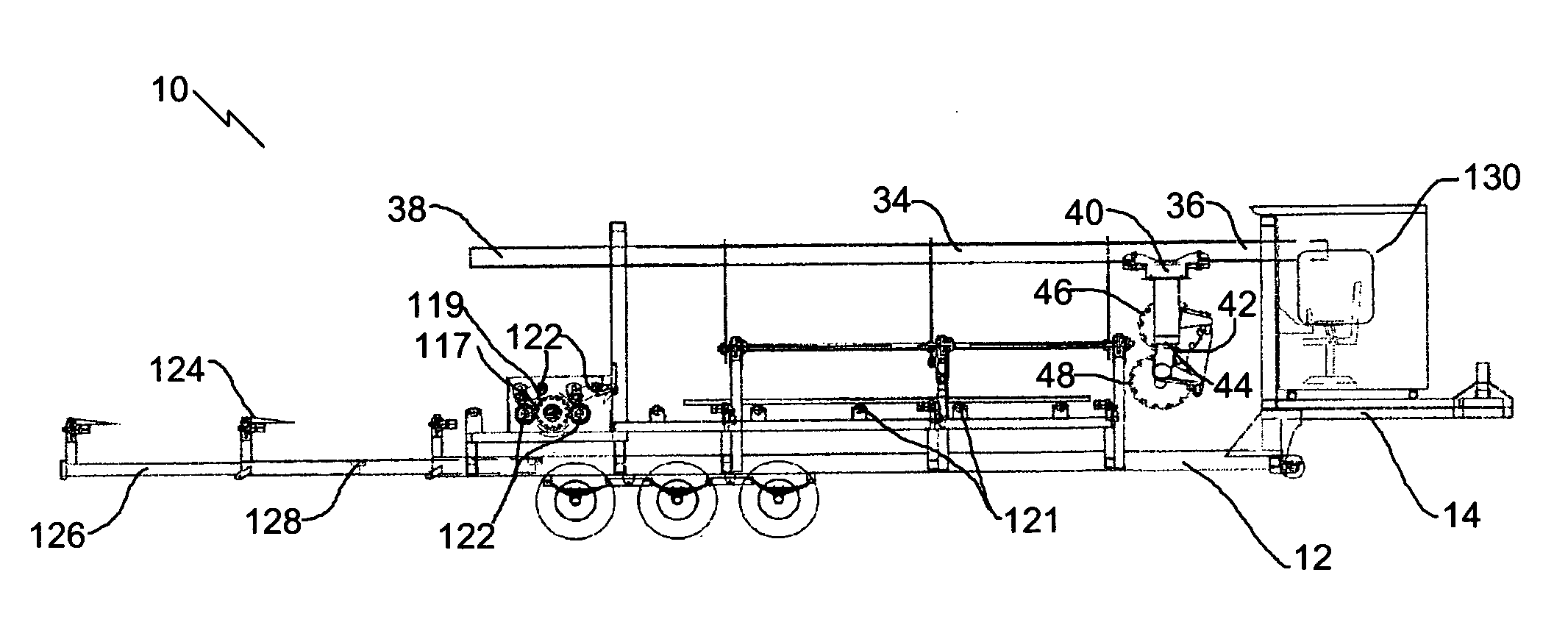
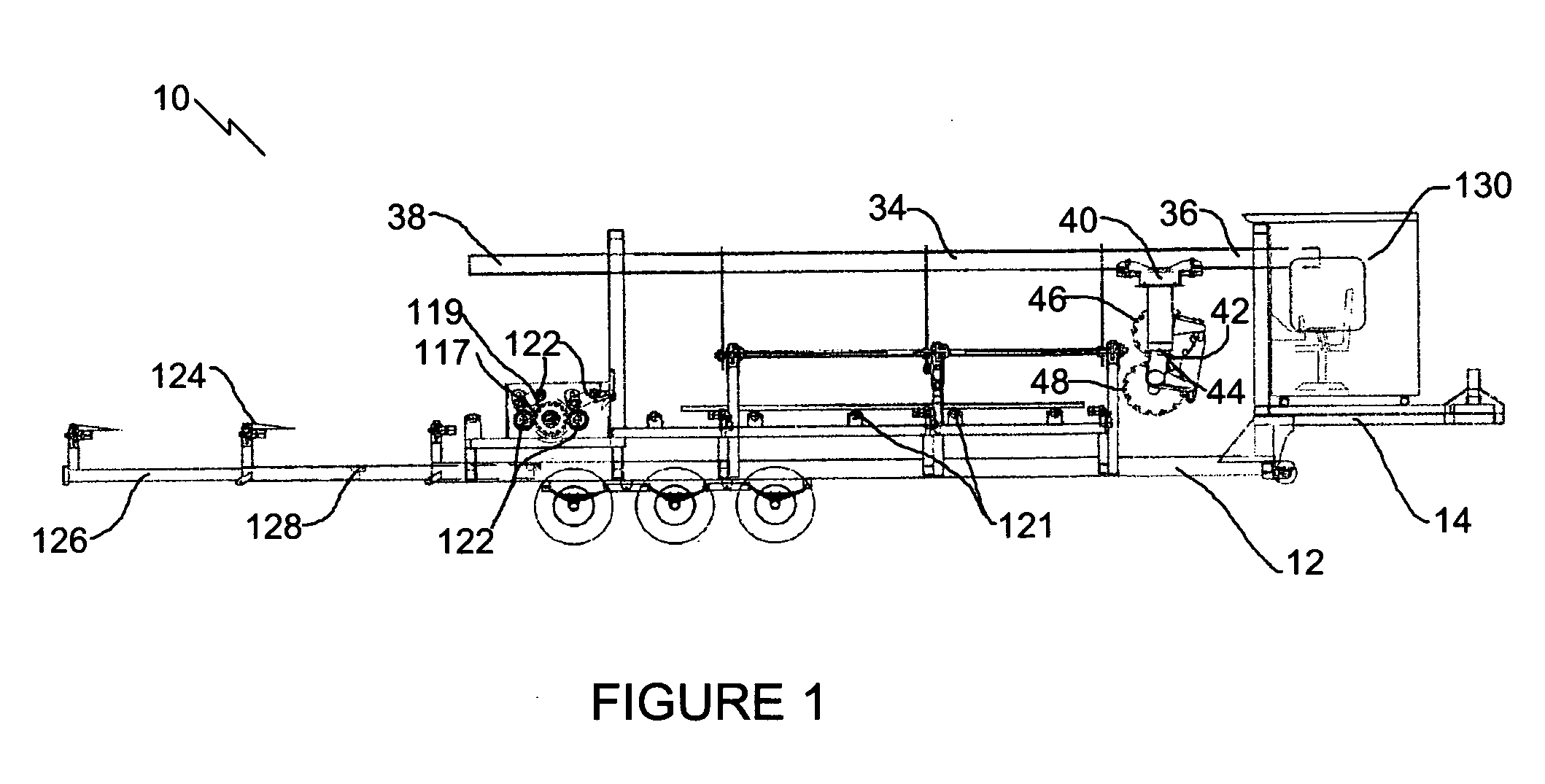
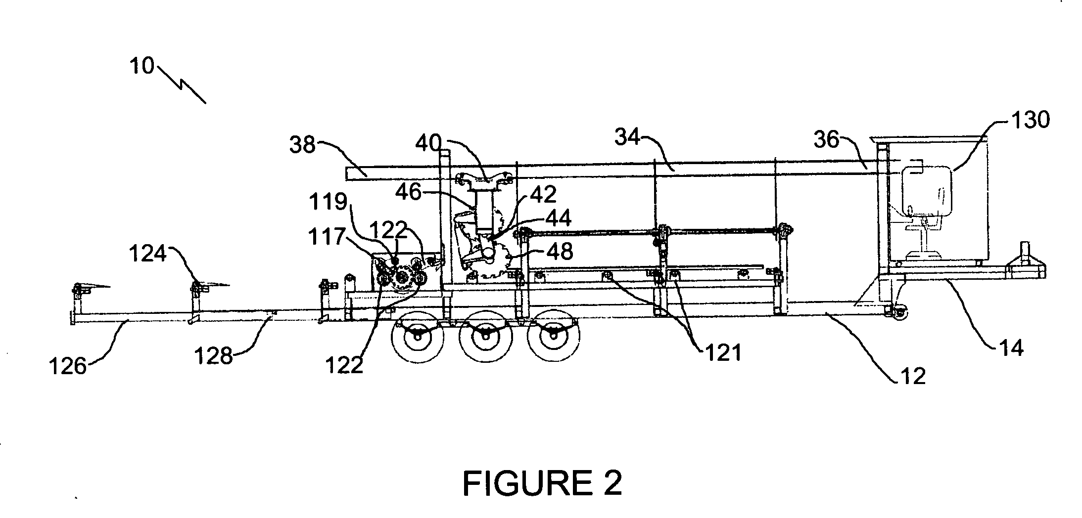
[0020] The preferred embodiment, a portable saw mill generally identified by reference numeral 10, will now be described with reference to FIGS. 1 through 21.

[0021] Structure and Relationship of Parts:

[0022] Referring now to FIG. 1, there is shown portable sawmill 10 with bi-directional cutting circular saws including a primary support structure 12 in the form of a trailer 14, such as a tractor trailer, adapted to be pulled by a tractor truck and having levelling jacks 15 illustrated in FIGS. 6 and 7. Referring to FIG. 7, trailer 14 is designed to be compact and has a top level 16, a second level 18, a third level 20, a fourth level (represented by outfeed transfer 124 shown in FIGS. 1 and 3) or fifth or bottom level 22. On top level 16 of trailer 14 is a log deck 24 which has a substantially vertical transport position as shown in FIG. 6, and a substantially horizontal operative position as shown in FIG. 7. Referring to FIG. 6, a telescopic actuator 25 is provided to move log dec...


PUM

PropertyMeasurementUnit
Angleaaaaaaaaaa
Forceaaaaaaaaaa
Diameteraaaaaaaaaa

Abstract

A portable sawmill with bidirectional cutting circular saws includes a saw support pivotally mounted to a primary support structure for pivotal movement about a pivot axis which is transverse to the direction of movement. Two circular saws are rotatably mounted one above the other on the saw support. A first one of the two circular saws rotates in a first rotational direction and a second one of the two circular saws rotates in a second rotational direction. The teeth on both of the two circular saws are always moving toward a log resting on the log support as the log is being cut. An actuator is provided for selectively pivoting the saw support to invert the positioning of the two circular saws so that the teeth on both of the two circular saws continue to move toward the log being cut upon a change in direction occurring.

Description


Claims


Application Information

Patent Timeline
Owner FENTON DAVID S
Why Eureka
Try Eureka