
Blind cutter

a blind cutter and cutting head technology, applied in the field of blind cutters, can solve the problems of hardly ensuring the good affecting the quality of blind cutters, so as to achieve good quality of finished products and long service li

Inactive Publication Date: 2006-08-17
NIEN MADE ENTERPRISE CO LTD
View PDF0 Cites 44 Cited by
  • Summary
  • Abstract
  • Description
  • Claims
  • Application Information

AI Technical Summary

Benefits of technology

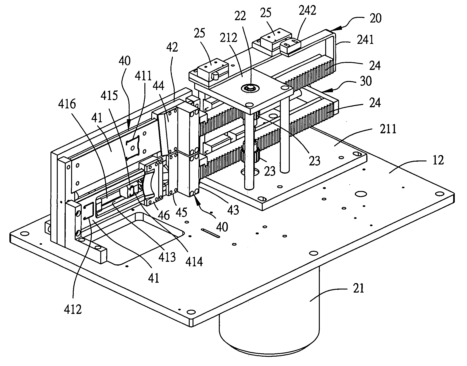
[0008] The key point in the invention is that each knife module is separately moved laterally by gears and racks so that the force exercising point and the force receiving point form a straight line, avoiding happening of twisting torque so that the transmitting structure of the drive device may not be damaged by twisting torque and accordingly the components can have a long service life, ensuring the good quality of finished products, with the knife module possible to be altered with that with other sizes to match with different kinds of blinds.

Problems solved by technology

Conventional blind cutters are very simple, can cut only one size and also are operated manually without any guide devices or positioning devices, taking much time and work, hardly ensuring the good quality of cut blinds.
So in cutting process, the bias distances may produce twisting torque, which may cause damage to the relative transmitting components of the knife modules and the pushing device, Besides, The knife of each knife module has to be assembled together or taken off the knife base, not designed to form an independent unit.
Therefore, in replacing a knife with new one, it must be assembled with the knife base, and adjusted together for correcting the cutting location of the knife, quite inconvenient in handling, in addition to difficulty for ensuring the accuracy of the sizes of cut blinds.

Method used


Image

  • Blind cutter
  • Blind cutter
  • Blind cutter

Examples


Embodiment Construction

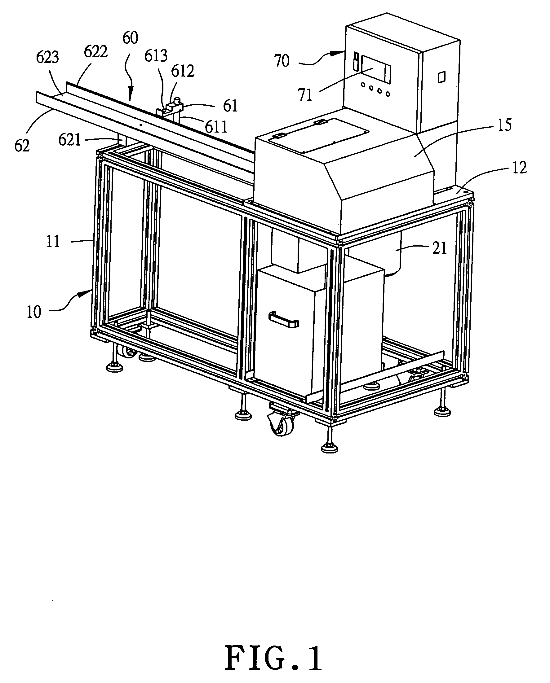
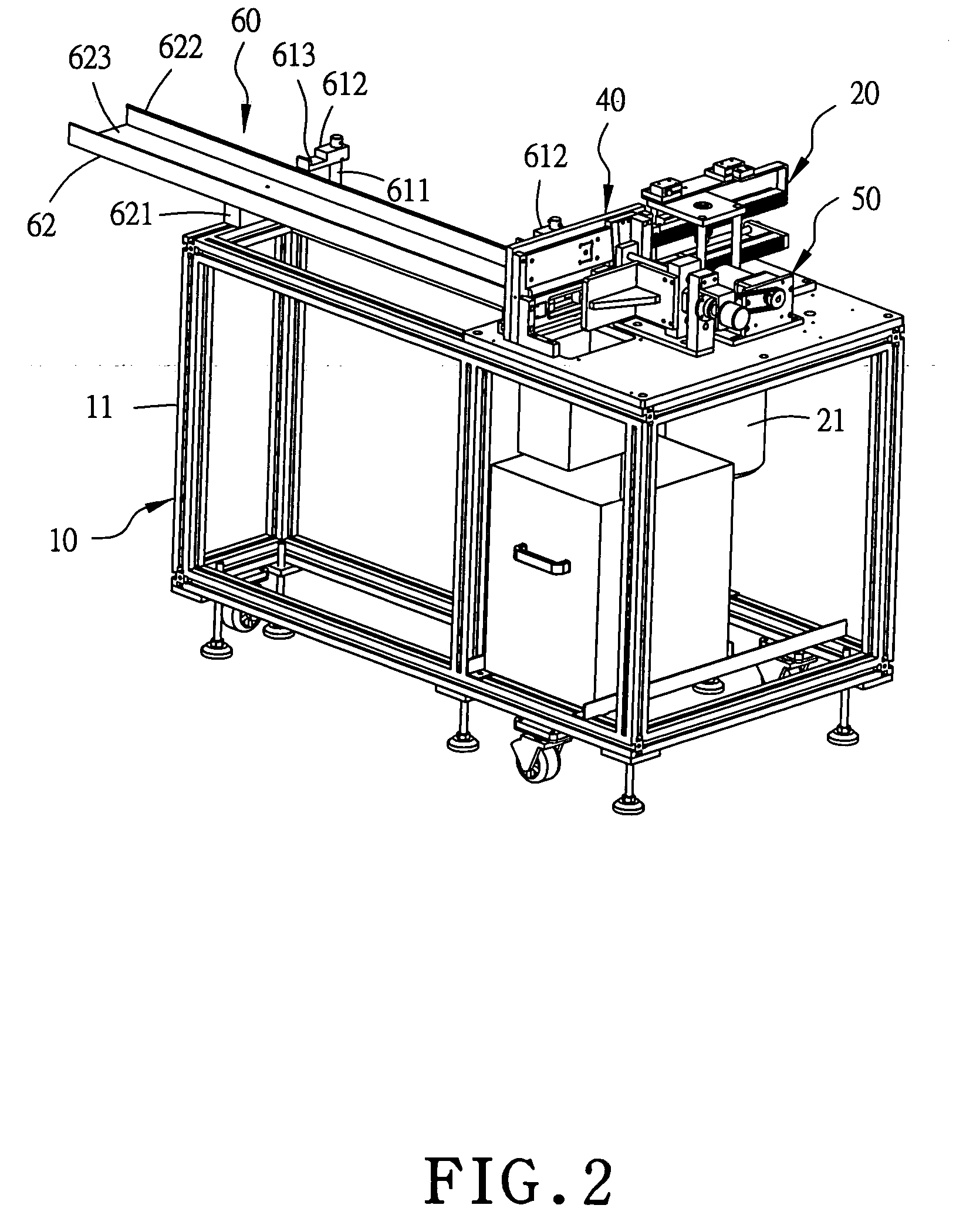
[0019] A preferred embodiment of a blind cutter in the present invention, as shown in FIGS. 1 and 2, includes a worktable 10, a drive device 20, a pressure absorbing device 30, two knife modules 40, a stop device 50, a guide device 60 and a control case 70.

[0020] The work table 10 is composed of a foot frame 11, a table 12 fixed on a proper location on the upper surface of the foot frame 11, and a module base fixing plate 13 fixed on a proper location on the table 12, as shown in FIG. 6. The module base fixing plate 13 has a vertical plate 131 and a guide base 14 fixed at the rear surface, and the vertical plate 13 is bored with a horizontal elongate slot 132. Further, a shell 15 is provided to cover on the worktable 10 for protecting the components fixed on the table 12.

[0021] The drive device 20, as shown in FIGS. 3, 4 and 5, consists of a speed-reducing motor 21, a fix plate 211 fixed on the speed-reducing motor 21 and also fixed on the table 12 of the work table 10, and a shaf...


PUM

PropertyMeasurementUnit
Lengthaaaaaaaaaa
Pressureaaaaaaaaaa
Elasticityaaaaaaaaaa

Abstract

A blind cutter includes at least a worktable, a drive device, and a number of knife modules. The drive device has a speed-reducing motor for rotating a rotary shaft, and a number of gears fixed on the rotary shaft to engage and move a number of racks. The knife modules respectively have a module base arranged lengthwise on the work table, having a special hole for special blinds to pass through, with a knife fitted in slidably and respectively moved by the racks for cutting a blind material respectively extending on the module bases.

Description

BACKGROUND OF THE INVENTION [0001] 1. Field of the Invention [0002] This invention relates to a blind cutter, particularly to one possible to cut many different sizes and types of blinds such as vertical blinds and lateral blinds. [0003] 2. Description of the Prior Art [0004] There are no special regulations for the sizes of window blinds, so special blind cutters have to be used for each kind of blind having different lengths and width. [0005] Conventional blind cutters are very simple, can cut only one size and also are operated manually without any guide devices or positioning devices, taking much time and work, hardly ensuring the good quality of cut blinds. There is also a conventional cutter using a motor for its power source, cutting with plural knife modules driven synchronously by a pushing device for cutting blinds positioned on each knife module. [0006] However, the conventional electric cutter has a pushing device for the knife of each knife module, and the force exercis...

Claims


Application Information

Patent Timeline
IPC IPC(8): B26D1/06
CPCB23D23/00B26D1/06B26D5/08B26D5/086Y10T83/8834Y10T83/8844
Inventor NIEN, MINGLEE, WEN-YEUCHEN, KUN-CHANGCHUANG, KUN-MING
Owner NIEN MADE ENTERPRISE CO LTD
Learn More