
Connector insulating boot for different sized conductors and associated methods

a technology of electrical insulation and boot, which is applied in the direction of dustproof/splashproof/drip-proof/waterproof/flameproof connection, cable termination, etc., can solve the problems of connector corrosion and failure, boots that do not permit water ingress, and may not be sufficient to keep water out, so as to increase the margin of error during installation and facilitate installation

Active Publication Date: 2006-08-17
THOMAS & BETTS INT INC
View PDF59 Cites 4 Cited by
  • Summary
  • Abstract
  • Description
  • Claims
  • Application Information

AI Technical Summary

Benefits of technology

[0008] In view of the foregoing background, it is therefore an object of the present invention to provide an electrical connector and insulating boot that is more easily installed and with an increased margin for error during installation.

Problems solved by technology

Unfortunately, water ingress, particularly where the boot is intended to seal against the jacket of the cable end, may result in corrosion and failure of the connector.
When properly installed, such boots do not permit water ingress.
Unfortunately, if improperly installed the seal provided by the boot may not be sufficient to keep water out.
Accordingly, water may enter and degrade the electrical connection resulting in premature failure of the connector.
Instances of improper installation are more likely to occur as training and skill levels are reduced, and while at the same time greater production rates are required.
For example, an improperly trained installer may cut the boot at a ring that is too large to correctly seal.
Months or years after installation, water may penetrate the area of the seal and cause connector failure.
Unfortunately, these also may fail to provide proper sealing and / or accommodate different sized cable ends.

Method used


Image

  • Connector insulating boot for different sized conductors and associated methods
  • Connector insulating boot for different sized conductors and associated methods
  • Connector insulating boot for different sized conductors and associated methods

Examples


first embodiment

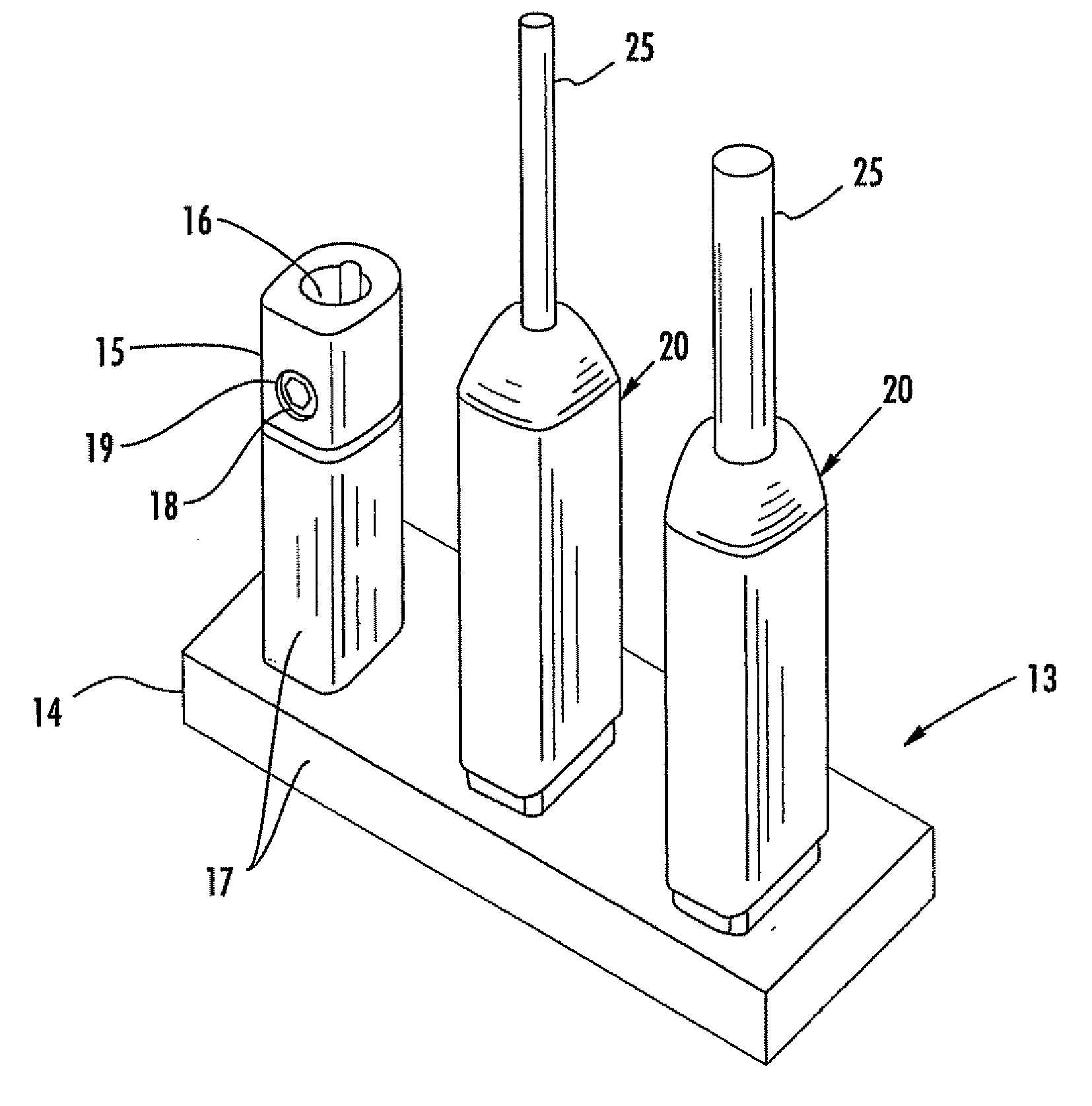
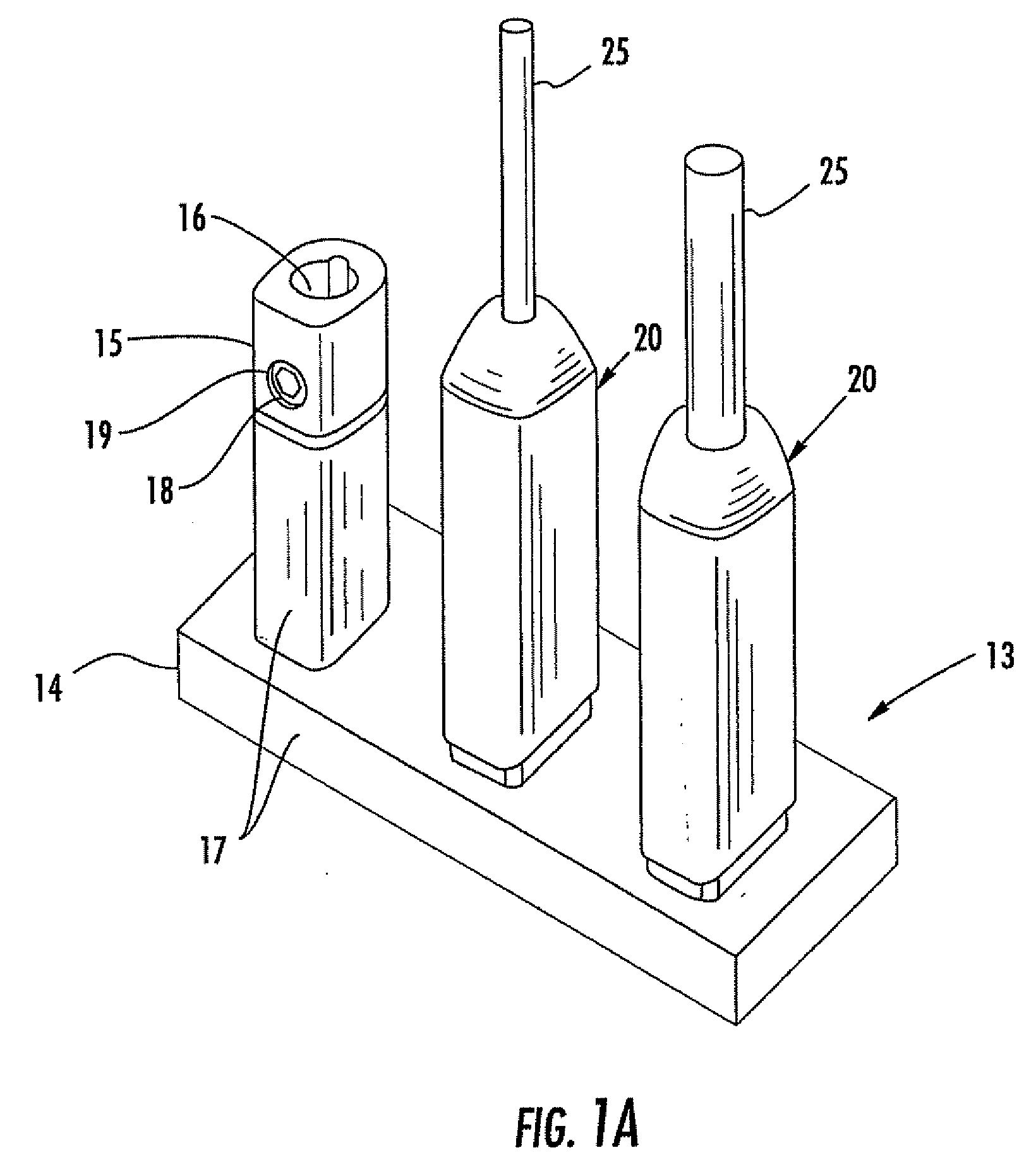
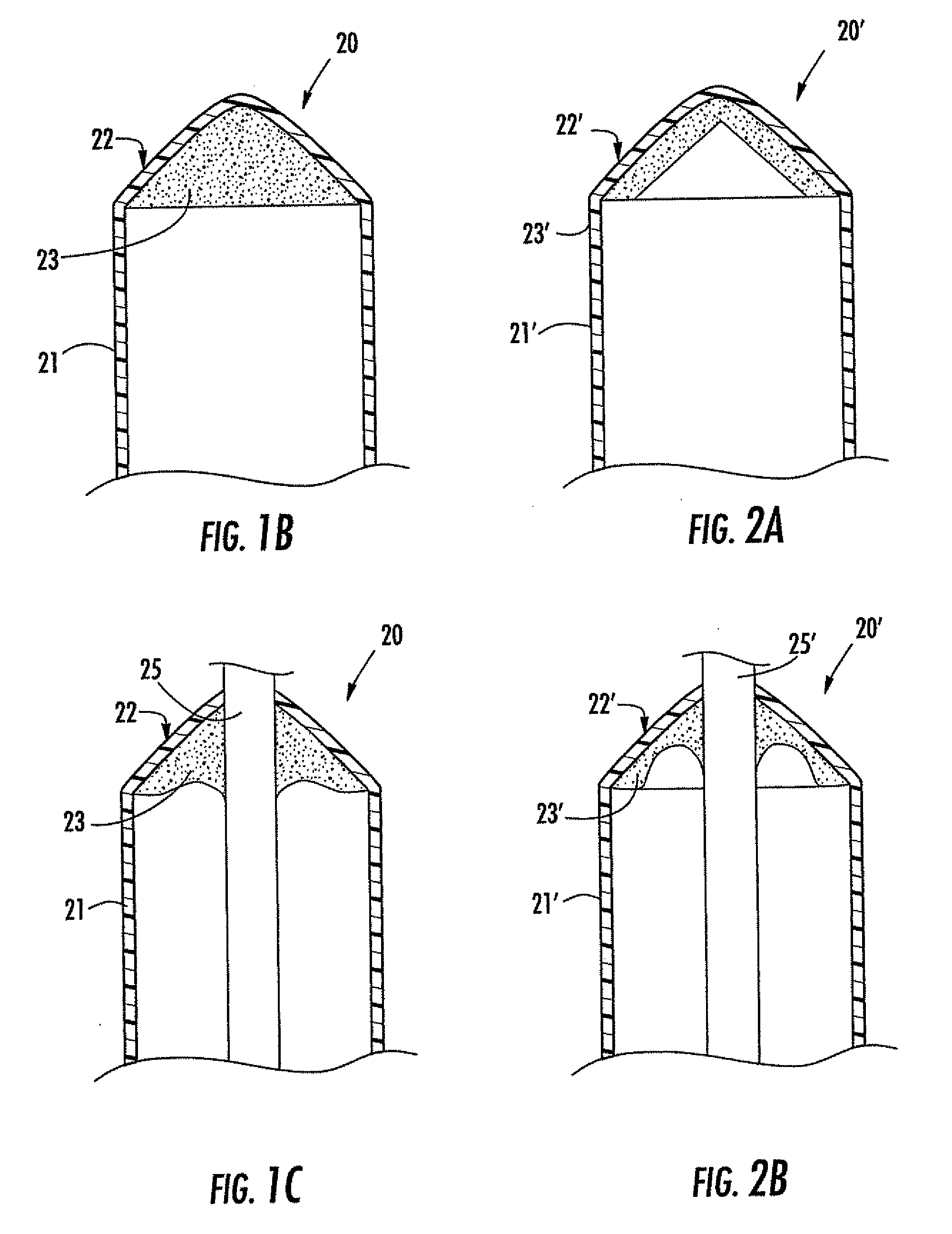
[0034] Referring initially to FIGS. 1A through 1C, an insulating boot 20 for an electrical connector 13 in accordance with the invention is now described. As shown in FIG. 1A, the electrical connector 13 includes a conductive body in the form of a bar-shaped bus 14 and a series of posts 15 extending upwardly therefrom. An insulating layer 17 is provided over the bus 14 and lower portions of the posts 15. Each post 15 includes a conductor receiving passageway 16 therein to receive the conductor of the corresponding cable end. As shown with reference to the leftmost post of FIG. 1A, the posts 15 of the conductive body also have a fastener receiving passageway 19 intersecting the at least one conductor receiving passageway 16. A fastener 18 is positioned in the fastener receiving passageway 19 for securing the conductor of the cable end as will be appreciated by those skilled in the art. As will also be appreciated by those skilled in the art, multiple fasteners can be used and other c...

second embodiment

[0039] Turning now to FIGS. 2A and 2B, the boot 20′ is now described. This embodiment is similar to that described above with reference to FIGS. 1B and 1C, but in this embodiment, the sealant material 23′ is in the form of a layer lining the interior of the end cap 22′. The other elements and operation are similar to that of the boot 20 described above and no further explanation is required.

third embodiment

[0040] Referring now to FIGS. 3A and 3B, an insulating boot 30 is now described. In this embodiment, the boot 30 includes a tubular sidewall 31 or insulating tube and an inverted end cap 32. More particularly, the inverted end cap 32 illustratively includes rounded over peripheral edges and a rupturable medial portion 34. The rupturable medial portion 34 is left unruptured if no cable is present on a given connector post as will be appreciated by those skilled in the art. If a cable 35 is positioned through the boot 30 (FIG. 3B) the rupturable medial portion 34 is ruptured as the cable end is forced therethrough. A seal is formed between the cable 35 and the adjacent portions of the end cap seal 32.

[0041] Additional seals may be provided to the inverted boot as shown by the embodiment of FIGS. 4A and 4B. In particular, in this embodiment the boot 30′ also includes a pair of ring-shaped wiper seals 36′, 37′ that extend inwardly toward an axis of the boot. These wiper seals 36′, 37′ p...


PUM


Abstract

An electrical connector may include a conductive body having a conductor receiving passageway therein to receive the conductor of a cable end. The conductive body may also have a fastener receiving passageway intersecting the conductor receiving passageway, and a fastener may be positioned in the fastener receiving passageway for securing the conductor. The connector may also include an insulating boot associated with the conductor receiving passageway. The insulating boot may include an insulating tube, and at least one rupturable seal closing the insulating tube and rupturing upon initial insertion of the cable end therethrough. The rupturable seal may also be compliant to accommodate different sized cable ends and form a seal with adjacent portions of the cable end. A pair of seals may be provided with an optional sealant material therebetween.

Description

RELATED APPLICATION [0001] This application is based upon prior filed copending provisional application Ser. Nos. 60 / 448,019 filed Feb. 18, 2003 and 60 / 499,144 filed Aug. 29, 2003. The entire subject matter of both provisional applications are incorporated herein by reference in their entirety.FIELD OF THE INVENTION [0002] The invention relates to the field of electrical connectors, and, more particularly, to electrical insulator boots used in electrical connectors for electrical distribution systems and associated methods. BACKGROUND OF THE INVENTION [0003] Underground and submersible junction bus connectors are widely used in electrical power distribution systems. One type of such connector is offered under the designation SWEETHEART® by Homac Mfg. Company of Ormond Beach, Fla., the assignee of the present invention. The SWEETHEART® connector is a cast or welded aluminum connector including an elongate bus portion and a series of tubular posts extending outwardly from the bus port...

Claims


Application Information

Patent Timeline
Patent Type & Authority Applications(United States)
IPC IPC(8): H01R9/05H01R4/70H01R13/52H01R43/00
CPCH01R4/70H01R13/5205H01R13/5213H01R13/5216H01R13/5837H01R43/005H01R13/523
Inventor CAWOOD, MATTHEW D.JAZOWSKI, ROY E.SALERNO, MARC F.ZAHNEN, JAMES L.
Owner THOMAS & BETTS INT INC
Learn More