Sheet feeder

a feeder and sheet technology, applied in the field of sheet feeders, can solve the problems of large gap, holder deformation, and sheet being fed is likely to be creased at its end portion, and achieve the effect of preventing or reducing the damage of the recording medium

Active Publication Date: 2006-08-17
BROTHER KOGYO KK
View PDF7 Cites 32 Cited by
  • Summary
  • Abstract
  • Description
  • Claims
  • Application Information

AI Technical Summary

Benefits of technology

[0010] Aspects of the invention relate to a sheet feeder designed to feed a recording medium to an image reading unit and may prevent or reduce damage of the recording medium.

Problems solved by technology

However, in the structure disclosed in Japanese Laid-Open Patent Publication No. 2002-173240, a large gap exists between a position where the inclined separation face plate is provided and a position where the inclined separation face plate is not provided, and a sheet being fed is likely to be creased at its end portion.
On the other hand, if the sheet separating portion formed of metal sheet disclosed in Japanese Laid-Open Patent Publication No. 2004-149297 is provided at the inclined separation face plates located on the downstream side of the cassette body disclosed in Japanese Laid-Open Patent Publication No. 2002-173240, the holder may be deformed due to a pressing force generated when the sheet is fed by the sheet feed roller, the protrusions may greatly protrude from the long holes in the holder, the sheet may be strongly rubbed by the protrusions and a surface of the sheet may be easily damaged.
As a result, a surface (recorded surface) of the glossy paper may be easily damaged.
Furthermore, if the protrusions are shaped in the form of a claw, scratches on the surface of the sheet may appear and be deep.

Method used


Image

  • Sheet feeder
  • Sheet feeder
  • Sheet feeder

Examples


Embodiment Construction

[0031] It is noted that various connections are set forth between elements in the following description. It is noted that these connections in general and, unless specified otherwise, may be direct or indirect and that this specification is not intended to be limiting in this respect.

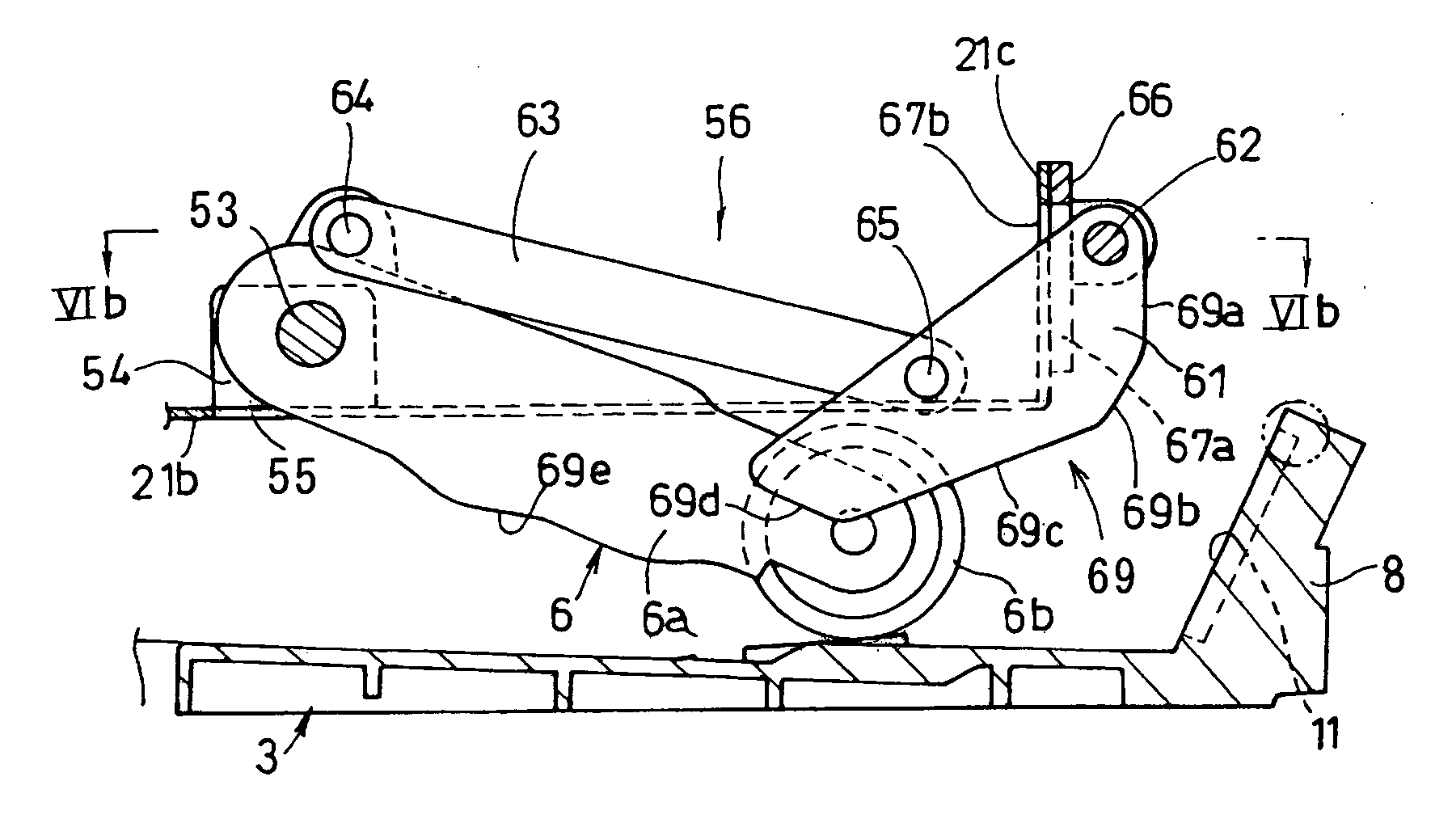
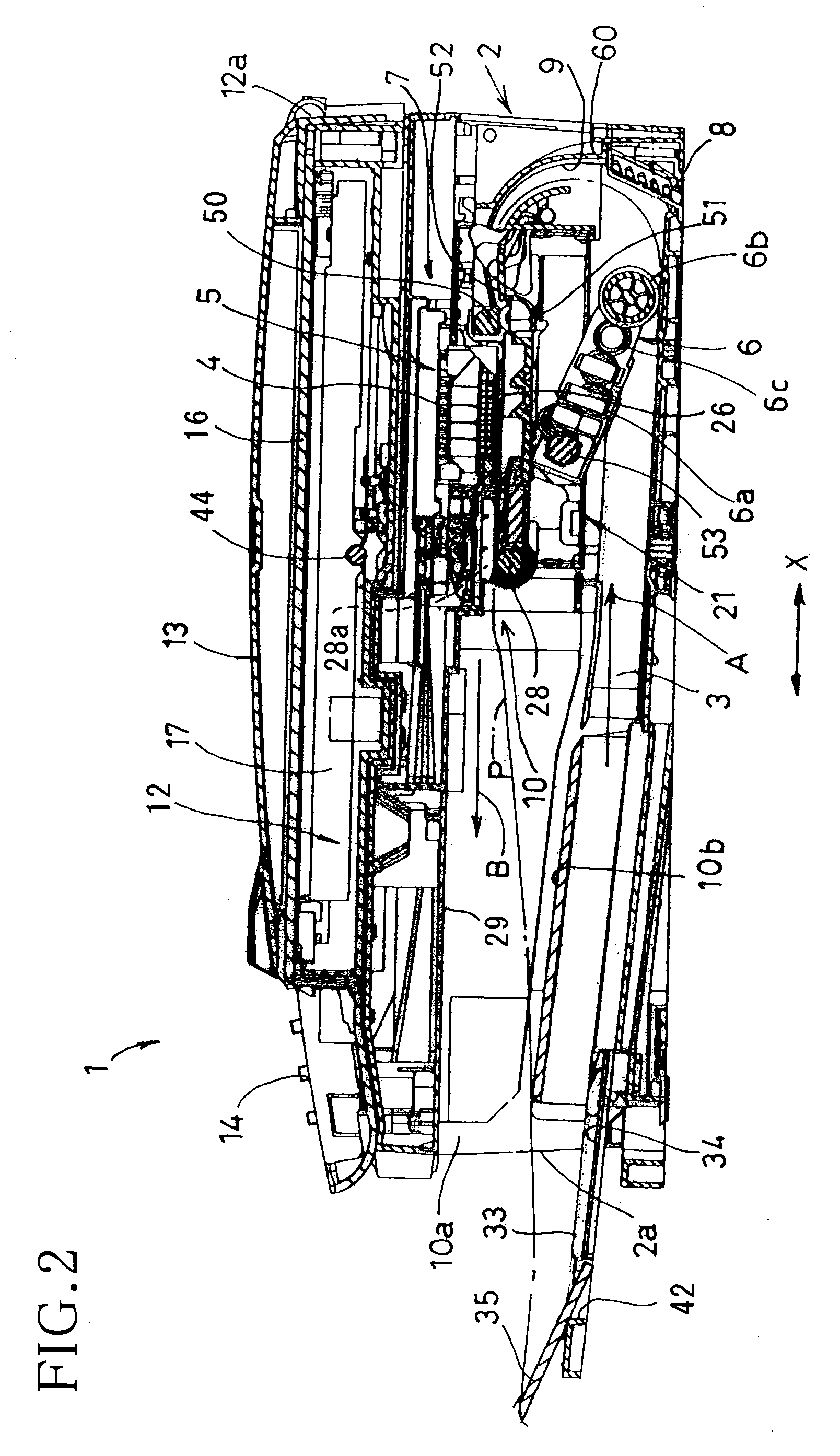
[0032] According to one aspect of the disclosure, a sheet feeder may include a cassette body capable of storing a number of recording sheets in a stack; a sheet feed roller capable of feeding an uppermost recording sheets in the stack; an inclined separation plate that is provided on a downstream side of the cassette body with respect to a sheet feeding direction, the inclined separation plate extending in a direction perpendicular to the sheet feeding direction; and a separation member that is attached to the inclined separation plate, the separation member capable of separating the recording sheets one-by-one from the stack in cooperation with the sheet feed roller. The separation member has a number...


PUM


Abstract

Sheets are separated one-by-one from their stack placed in a holder by a sheet feed roller and a separation member provided in an inclined separation plate. The separation member can be a flat metal plate, and possibly includes a base portion, arm portions extending from the base portion, separation protrusions provided on the arm portions and capable of contacting a sheet, and elastic legs extending from the base portion. The arm portions, the separation protrusions, and the elastic legs can be arranged along a sheet feeding direction. The inclined separation plate may be provided with window holes on a central portion with respect to a direction perpendicular to the sheet feeding direction. The window holes can allow each separation protrusion or two or more separation protrusions to protrude toward the front surface of the inclined separation plate. Bridge portions can be provided between adjacent window holes. The bridge portions may strengthen the bending stiffness of the inclined separation plate in the direction perpendicular to the sheet feeding direction, and thus the separation protrusions are allowed to protrude only by a specified amount as designed.

Description

CROSS REFERENCE TO RELATED APPLICATION [0001] This application claims priority from Japanese Patent Application No. 2004-376507, filed on Dec. 27, 2004, the entire subject matter of which is incorporated herein by reference. BACKGROUND [0002] 1. Technical Field [0003] Aspects of the invention relate to a sheet feeder capable of separating sheets one-by-one from a stack of the sheets in a holder by a sheet feed roller and a separation member having elasticity. [0004] 2. Related Art [0005] Image recording apparatuses such as a printer, a copier, a facsimile machine, generally include a sheet feeder that separates cut sheets (recording sheets) one-by-one and feeds them to an image recording unit. [0006] In Japanese Laid-Open Patent Publication No. 2002-173240, cut sheets are accommodated substantially horizontally in an open-top box shaped cassette body, inclined separation face plates are provided at established intervals in a sheet width direction and on a downstream side of the cass...

Claims


Application Information

Patent Timeline
Patent Type & Authority Applications(United States)
IPC IPC(8): B65H3/52
CPCB65H3/0661B65H3/5215B65H3/56B65H2404/54B65H2405/11151B65H2405/1136B65H2405/141
Inventor ASADA, TETSUO
Owner BROTHER KOGYO KK
Why Eureka
Try Eureka