Cabinet drawer drivingly connected locking mechanism

a technology of locking mechanism and cabinet drawer, which is applied in the direction of building locks, domestic applications, construction, etc., can solve the problems of time-consuming and inconvenient for users, inconvenient operation and assembly of the above locking mechanism, and quite difficult assembly of the locking mechanism

Inactive Publication Date: 2006-08-17
SUPER TEST CORP
View PDF18 Cites 14 Cited by
  • Summary
  • Abstract
  • Description
  • Claims
  • Application Information

AI Technical Summary

Benefits of technology

[0005] It is a primary object of the present invention is to provide a cabinet drawer drivingly connected locking mechanism that can lock all the drawers at one time. And the locking and unlock state of the cabinet drawers can both be controlled by the opening and closing operation of the top cover of the cabinet.

Problems solved by technology

But a user has to use the tools inside the cabinet right after the cabinet is being transported, it will be time-consuming and inconvenient for the user to lock the drawers one by one before transporting the cabinet.
However, the above locking mechanism is quite difficult to assemble and the exertion of the second driving force is acceptable but very inconvenient.
All the other patents are using additional key unit to rotate the link design manually for locking and unlock the drawer which is very inconvenient.
This will not only causing inconveniency to actual operation and assembly, the shifting section will also damage the cover board easily which affect the overall aesthetic appealing.

Method used


Image

  • Cabinet drawer drivingly connected locking mechanism
  • Cabinet drawer drivingly connected locking mechanism
  • Cabinet drawer drivingly connected locking mechanism

Examples


Embodiment Construction

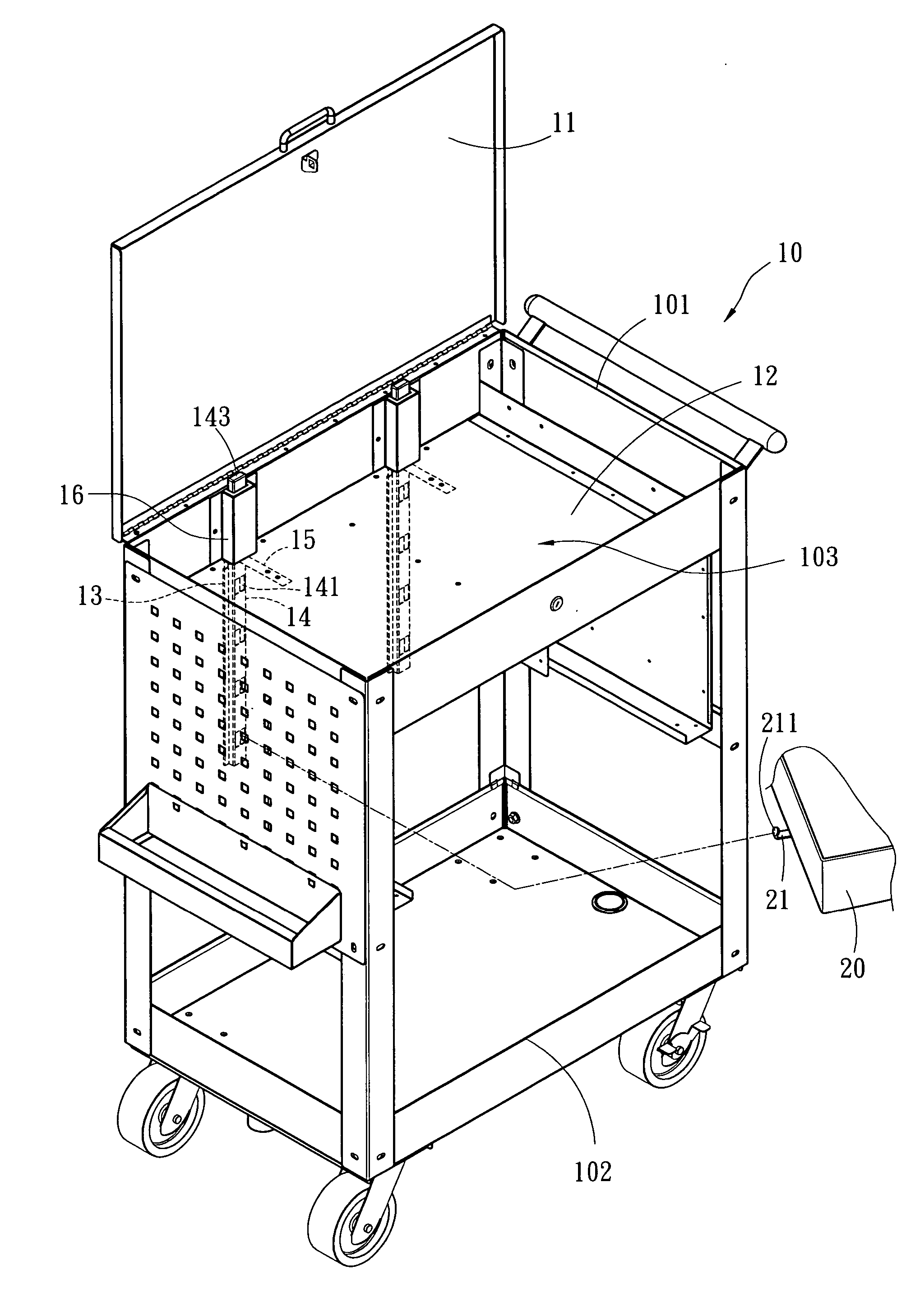
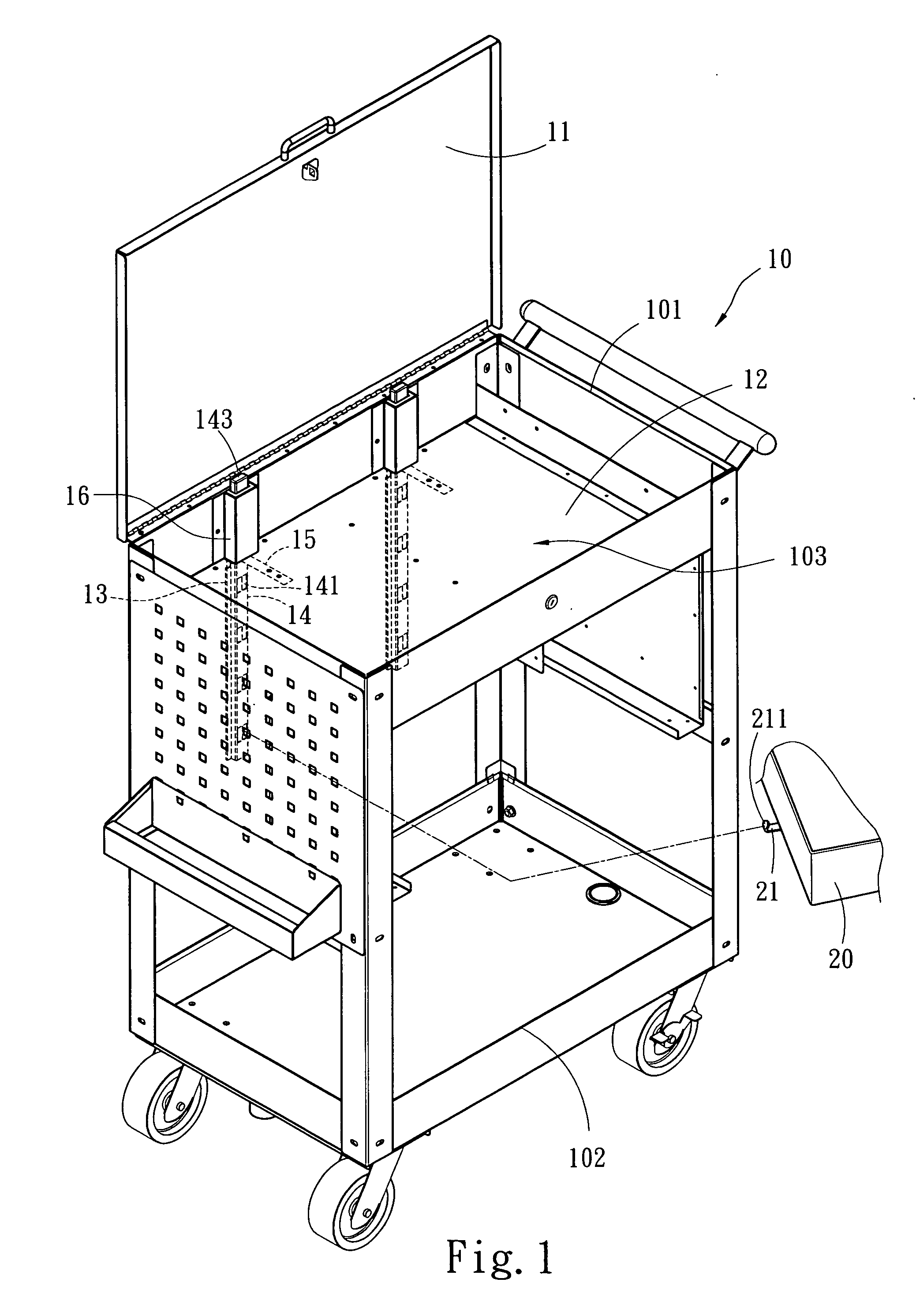
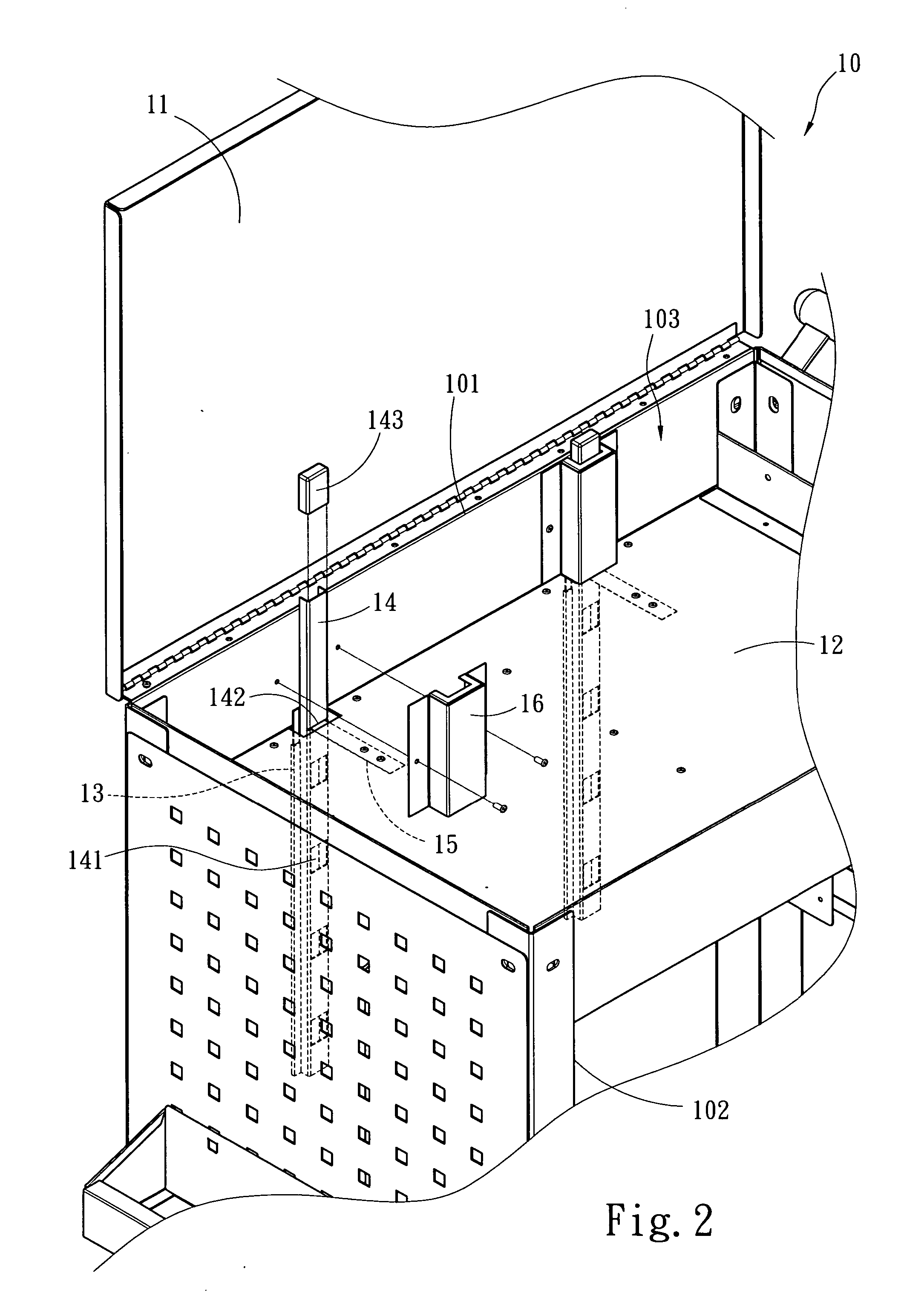
[0011] Please refer to FIGS. 1 and 2, showing a perspective view of a preferred embodiment of the present invention and an exploded view of the locking mechanism. A cabinet body 10 includes an upper open side 101 and a lateral open side 102, a top cover 11 is arranged on the upper open side 101, and at least one partition 12 is arranged in the cabinet body 10 defining at least one compartment 103. At least one drawable and slidable drawer 20 is arranged in the lateral open side 102. At least one locking element 21 is disposed on each drawer 20 at the side which is corresponding to the inside edge of the lateral open side 102 when the drawer is drawn in. At least one locking mechanism includes a sliding seat 13 which is fixedly arranged in the cabinet body 10 correspondingly located at the opening and closing driving position of the top cover 11. A engaging body 14 located on the sliding seat 13, the engaging body 14 can be driven by the opening and closing operation of the top cover...


PUM


Abstract

A cabinet drawer drivingly connected locking mechanism which can be synchronously driven along by the opening and closing operation of the top cover of the cabinet body to complete the locking and unlocking state of cabinet drawers, including a sliding seat, an engaging body having an engaging hole and an elastic element, when the top cover is pressed on the engaging body, an anchoring hole of the engaging body will press against the elastic element causing it to bend and store elasticity, the engaging hole will be moved downwards to engage with the locking element so as to complete the locking state of the drawer, when the top cover is opened, the depressing force of the engaging body is released, the restored elasticity of the elastic element is released and carries the engaging body and the engaging hole to move upwards back to its original position, thus unlocked the drawer.

Description

FIELD OF THE INVENTION [0001] The present invention relates to a cabinet drawer drivingly connected locking mechanism and, more particularly, to a locking mechanism that can be synchronously driven along by the opening and closing operation of the top cover of the cabinet body to complete the locking and unlocking state of cabinet drawers BACKGROUND OF THE INVENTION [0002] In order to facilitate users to classify and reorganize the tools at home, there exists a so-called tool cabinet. Most existing tool cabinet comprises a body equipped by four sidewalls between four corner pods, one top cover and one base. The top of the body is an open end that can be opened or closed by the top cover. The interior of the cabinet body can install some partitions, the partitions and the top cover formed a compartment for storing tiny tools. And at least one sidewall having an open end which allows a sliding drawer to be horizontally inserted into the cabinet body. Since the cabinet may be moved abo...

Claims


Application Information

Patent Timeline
Patent Type & Authority Applications(United States)
IPC IPC(8): A47B95/00
CPCE05B63/143E05B65/462
Inventor HUNG, SUE-TSEN
Owner SUPER TEST CORP
Why Eureka
Try Eureka