Conductor Stringing Apparatus And Process

a technology of stringing apparatus and stringing process, which is applied in the direction of lifting device, overhead line/cable apparatus, hoisting equipment, etc., can solve the problems of noise and pollution generated, and achieve the effect of reducing noise and emissions

Active Publication Date: 2009-10-29
TSE INT
View PDF10 Cites 14 Cited by
  • Summary
  • Abstract
  • Description
  • Claims
  • Application Information

AI Technical Summary

Benefits of technology

[0008]An electric drive system powered by an on-board battery bank to run a drum puller-tensioner used in the utility industry is disclosed and claimed. Further, a multi-drum puller-tensioner or bullwheel tensioner may be used employing the principles expressed herein. The battery bank (renewable energy storage) is to be of sufficient voltage and capacity to allow operation for a minimum of two hours at maximum rated torque and speed. Tensioning is achieved by magnetic coupling of the rotor and stator of the electric motor. Although it is preferred to use an ...

Problems solved by technology

Some of these lines require periodic replacement and/or upgrade and considerable noise and pollution is generated by internal combustion engines which pow...

Method used


Image

  • Conductor Stringing Apparatus And Process
  • Conductor Stringing Apparatus And Process
  • Conductor Stringing Apparatus And Process

Examples


Embodiment Construction

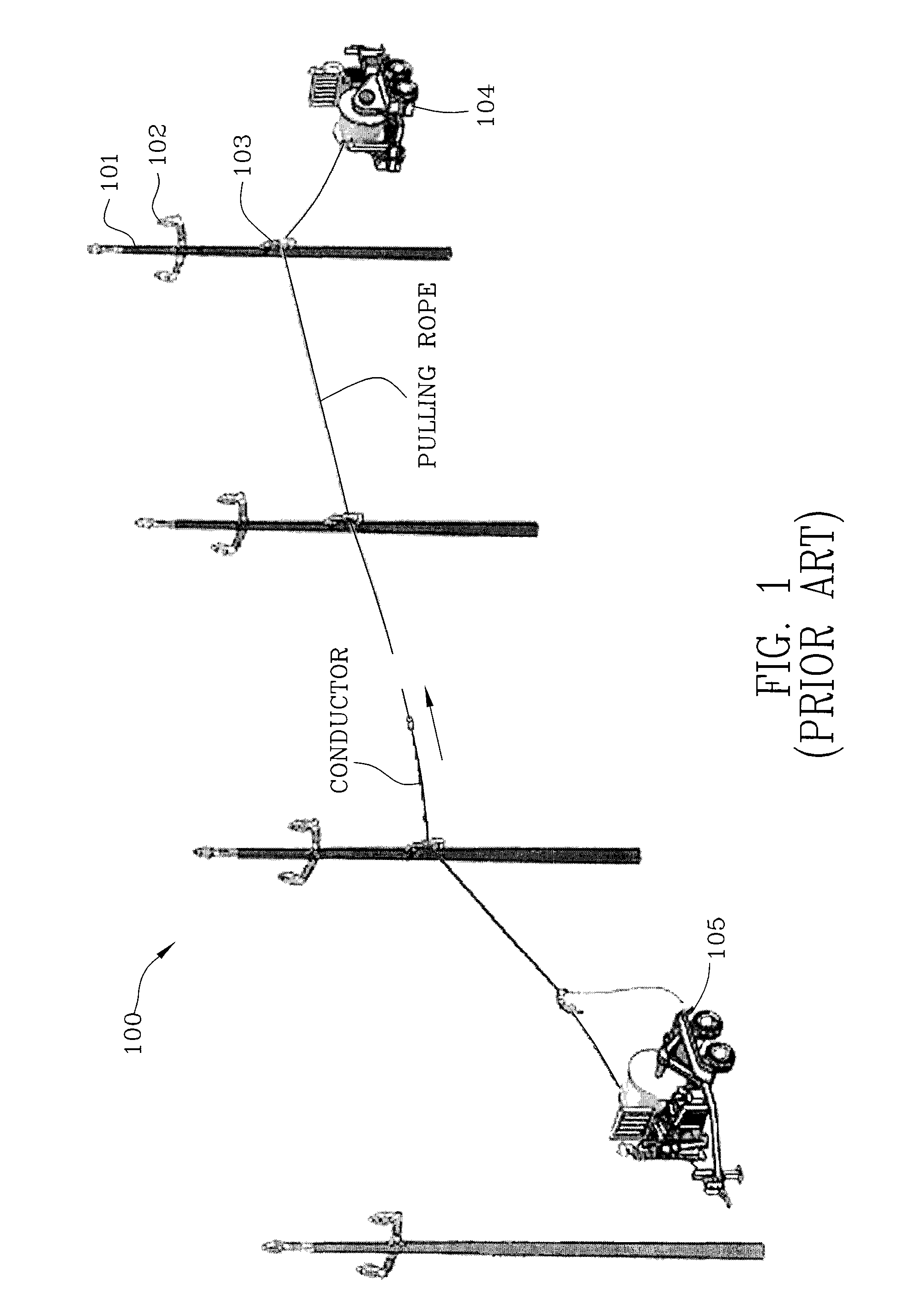
[0064]FIG. 1 is an illustration 100 of a conductor stringing tensioner 105 and puller 104. Poles 101 and insulators 102 are illustrated as is a conductor pulling rope and conductor. Insulators 102 and stringer attachment 103 are illustrated in FIG. 1 as is the traveling ground.

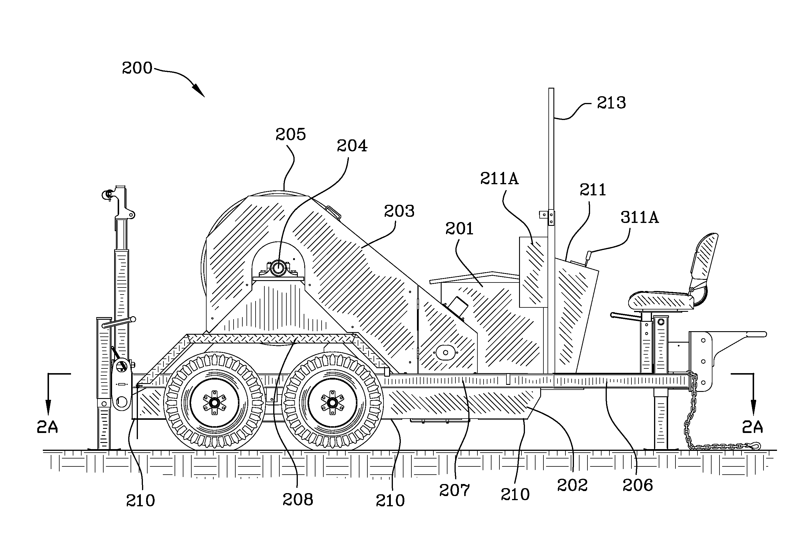
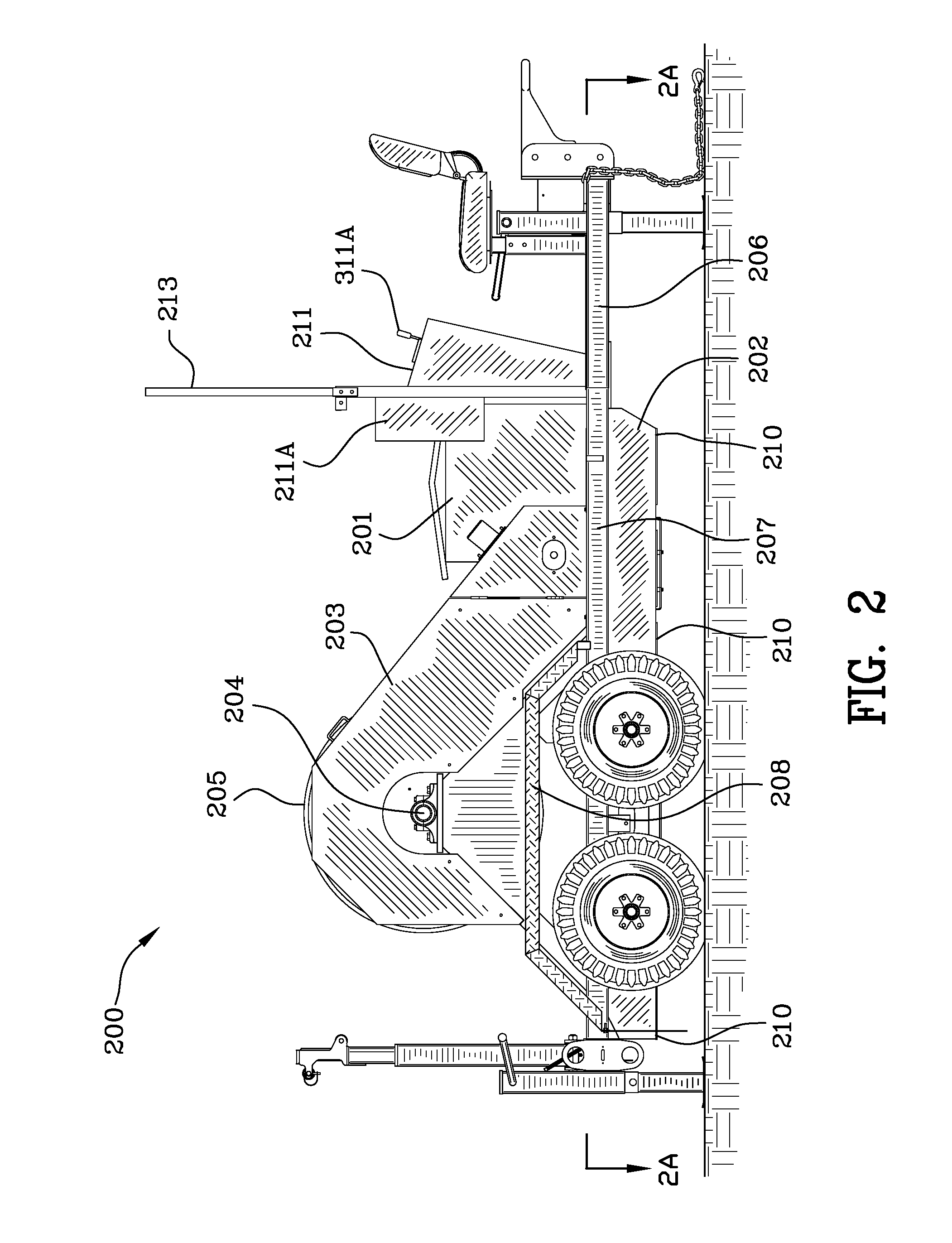
[0065]FIG. 2 is a side view 200 of the conductor stringing puller-tensioner of the instant invention illustrating the resistor bank cabinet 201, control panel 211, and control box housings 211A, 211B. An operator of the device is protected by a protective screen 213 in the event of a rope or conductor break under tension. Joystick 311A can be seen in FIG. 2 protruding from the control panel. Batteries are secured in an undercarriage formed of channel 210 which is obscured from view in FIG. 2 by battery skirt 202. Chain guard 203 protects a person from entanglement with a chain (not shown) which operates between a small sprocket (not shown) having 19 teeth per revolution and a large sprocket (not shown) having ...


PUM


Abstract

A line stringing apparatus includes in combination an electric motor, motor controller and a processor switchable between a pulling mode and a tensioning mode. An electric motor expends electrical energy when pulling the line and generates electrical energy when tensioning the line. The processor outputting commands to the motor controller for control thereof and for application of electrical energy from the batteries to the electric motor when in the pulling mode and for application of electrical energy generated by the electric motor to the plurality of batteries when in tensioning mode. The processor limits electric motor torque and speed based on operator commands for speed and torque in said pulling mode; and, the processor controlling electric motor torque in the tensioning mode.

Description

FIELD OF THE INVENTION[0001]The invention is in the field of conductor stringing apparatuses and processes.BACKGROUND OF THE INVENTION[0002]High voltage utility transmission lines are capable of supplying power over tens or hundreds of miles (or further) with minimal losses because of the very high voltages used. Step-up transformers located at utility power generation plants boost the voltage transmission levels up, depending on the particular utility, to and beyond 745 kV AC. At high voltages, power can be transmitted effectively as power transmission is a function of voltage times the current times the cosine of the phase angle between the voltage and the current. Use of high voltage minimizes current in the lines which thus minimizes losses which can be generally expressed as current squared times the resistance of the transmission line (i.e., the conductor).[0003]Electrical demand in the United States and worldwide has steadily grown. Larger and more conductors are needed. Util...

Claims


Application Information

Patent Timeline
IPC IPC(8): B66F19/00
CPCH02G1/02
Inventor JOHNSON, DUTCHMARTIN, JOHN J.
Owner TSE INT
Why Eureka
Try Eureka