Configurations and methods of high pressure acid gas removal

a technology of acid gas removal and high pressure, which is applied in the direction of liquefaction, lighting and heating apparatus, and separation processes, etc., can solve the problems of high energy consumption, high energy demand, and high co2 emissions of gas processing plants using these resources, so as to reduce/or heating, the effect of recovering energy and reducing the demand for external cooling

Active Publication Date: 2014-04-15
FLUOR TECH CORP
View PDF11 Cites 15 Cited by
  • Summary
  • Abstract
  • Description
  • Claims
  • Application Information

AI Technical Summary

Benefits of technology

[0007]The present invention is directed to various plant configurations and methods of acid gas removal from a feed gas using a physical solvent where the solvent is regenerated using successive flashing stages and low-level waste heat from various, and most typically at least one or two distinct sources. Especially preferred waste heat sources include compressor discharges of the refrigeration system and / or CO2 compression system, or (low level) heat content from the feed gas. Moreover, the methods and plants according to the inventive subject matter employ pressure letdown of the rich solvent by hydraulic turbines to further recover energy. Therefore, devices with high energy demand such as steam regenerators or stripping vessels can be avoided, and demand for external cooling and / or heating can be significantly reduced.

Problems solved by technology

However, due to the relatively high carbon contents of these resources, CO2 emissions from gas processing plants using these resources are often unacceptably high and generally require CO2 capture and sequestration.
Similarly, syngas or hydrogen production from gasification has often unacceptably high acid gas content, which necessitates removal and sequestration of CO2 to minimize greenhouse gas effects.
Unfortunately, sequestration of CO2 requires compression to a very high pressure (e.g., 2000 psig or higher), which is energy intensive, especially where CO2 is produced at or near atmospheric pressure from conventional gas treating processes.
While such plants and methods are relatively effective in CO2 removal from high-pressure feed gases, the produced CO2 is at or near atmospheric pressure and so requires substantial expenditure of energy for injection into the formation.
While such configurations reduce the energy demand for CO2 recompression at least to some degree, a relatively large demand for energy is required for the generation of steam used in the solvent heating.
Thus, although various configurations and methods are known to remove acid gases from different feed gases, all or almost all of them suffer from one or more disadvantages.

Method used


Image

  • Configurations and methods of high pressure acid gas removal
  • Configurations and methods of high pressure acid gas removal
  • Configurations and methods of high pressure acid gas removal

Examples


Embodiment Construction

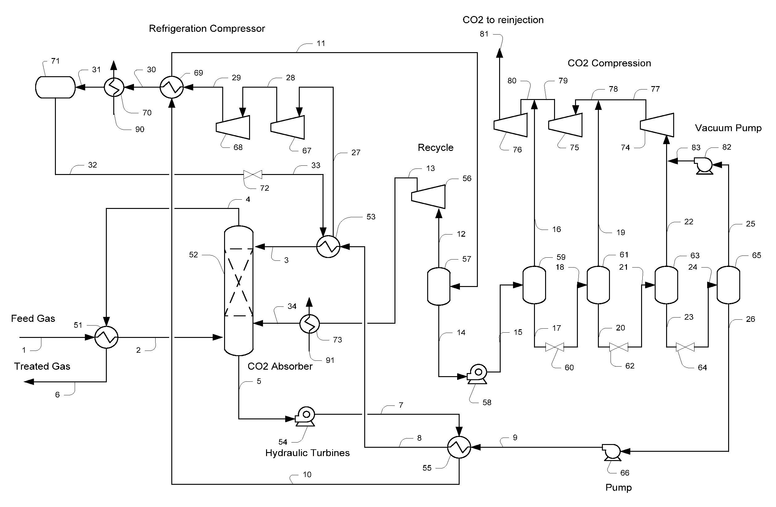
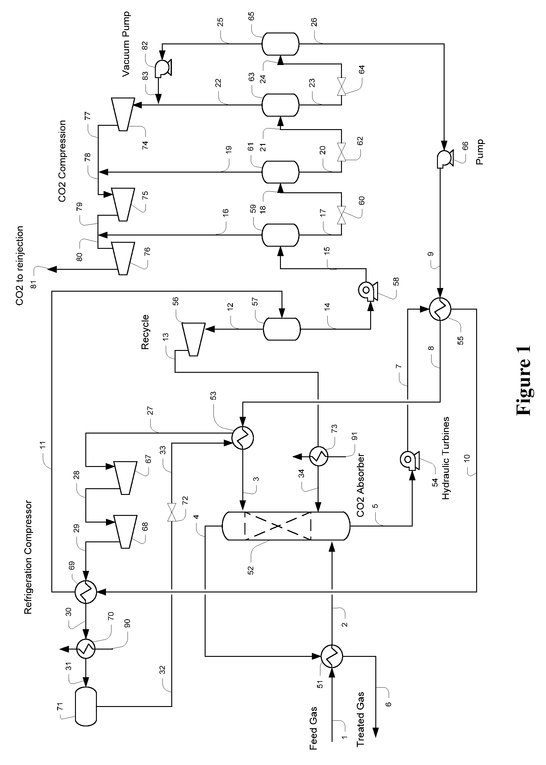
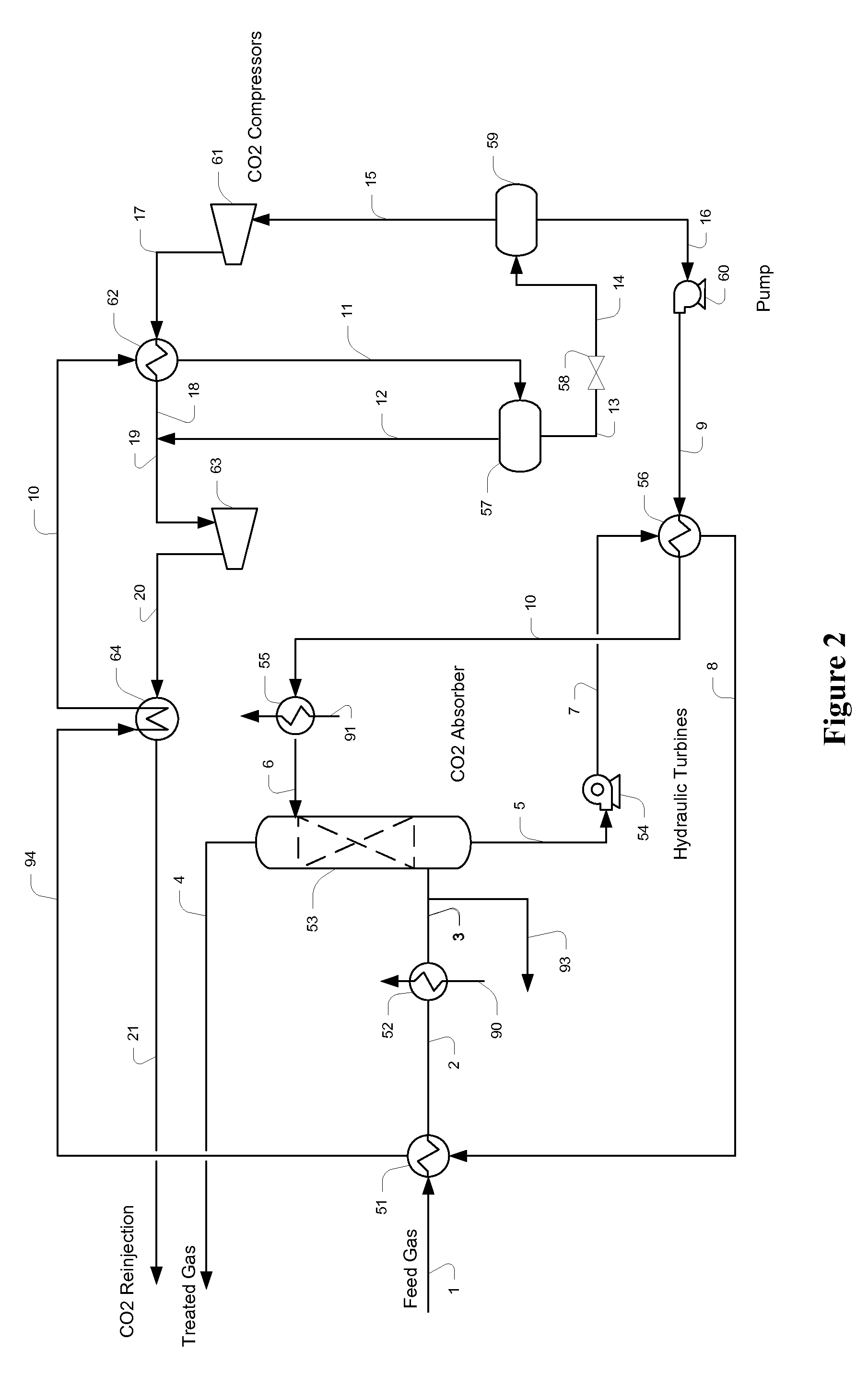
[0018]The inventor has discovered that acid gases can be removed from a feed gas that has relatively high pressure and CO2 content by absorbing the CO2 in a physical solvent to form a rich solvent, where the rich solvent is then heated and flashed to reduced pressure in several stages to so produce high-pressure CO2 product streams and a lean solvent. The lean solvent may be further flashed to a pressure below atmospheric pressure to so generate an ultra-lean solvent.

[0019]More specifically, it is preferred that contemplated methods of regenerating a CO2-rich physical solvent include those in which the rich solvent is heated and depressurized in multiple steps to atmospheric or sub-atmospheric pressure, wherein heating is performed at a temperature effective to allow removal of more than 50% of the CO2 from the solvent at a pressure above 100 psig to generate a CO2 product that need significantly less compression where the CO2 product is injected back into the formation or otherwise...


PUM

PropertyMeasurementUnit
temperatureaaaaaaaaaa
pressureaaaaaaaaaa
pressureaaaaaaaaaa

Abstract

Acid gas is removed from a feed gas using a physical solvent that is regenerated using successive flashing stages after heating of the rich solvent using low-level waste heat that is preferably produced or available within the acid gas removal plant. Especially preferred waste heat sources include compressor discharges of the refrigeration system and / or recompression system for CO2, and / or (low level) heat content from the feed gas.

Description

[0001]This application claims priority to our copending U.S. provisional patent application with the Ser. No. 61 / 102,053, which was filed Oct. 2, 2008.FIELD OF THE INVENTION[0002]The field of the invention is acid gas removal from hydrocarbonaceous feed gases, and particularly acid gas removal from natural and synthetic high pressure gases having high CO2 content and concurrent production of CO2 for re-injection.BACKGROUND OF THE INVENTION[0003]As low sulfur natural gas fields are being depleted, gas production from other sources is necessary to meet today's energy demands. With increasing energy costs, gas production from high acid gas natural gas fields and syngas production via gasification of carbonaceous materials are becoming economically attractive. High acid gas fields and coal mines are still plentiful in many parts of the world. However, due to the relatively high carbon contents of these resources, CO2 emissions from gas processing plants using these resources are often u...

Claims


Application Information

Patent Timeline
Patent Type & Authority Patents(United States)
IPC IPC(8): B01D53/14
CPCB01D53/1425B01D53/1456B01D53/1475B01D53/77B01D2257/504Y02C20/40
Inventor MAK, JOHN
Owner FLUOR TECH CORP
Why Eureka
Try Eureka