Vehicular Traffic Surveillance Doppler Radar System

a doppler radar and vehicle traffic technology, applied in the field of police radar systems, can solve the problems of difficult identification of vehicles whose speed is being displayed when multiple vehicles, inability to identify vehicles, and inability to achieve the detection of vehicles, etc., and achieve the effect of eliminating look-past errors

Active Publication Date: 2006-08-17
APPLIED CONCEPTS
View PDF50 Cites 19 Cited by
  • Summary
  • Abstract
  • Description
  • Claims
  • Application Information

AI Technical Summary

Benefits of technology

[0005] A system and method are disclosed that provide for a vehicular traffic surveillance Doppler radar which substantially eliminates look-past error by determining the range and speed of vehicles in multiple vehicle environments. In particular, the range of the target may be utilized in a comparative fashion in a multi-vehicle environment to determine which vehicle is closer or the closest. Also, the range of the target may be utilized in conjunction with the speed and heading of the target to determine the risk of a collision between the target and a patrol vehicle.

Problems solved by technology

It has been found, however, that the existing police Doppler radar systems are not necessarily successful in environments having multiple vehicles in position to reflect the radar signal.
In particular, identification of the vehicle whose speed is being displayed when multiple vehicles are in a position to reflect the radar signal has proven difficult due to “look-past error,” which occurs in situations where the intended target vehicle in the foreground has a significantly smaller radar cross-section than an unintended target vehicle in the background.

Method used


Image

  • Vehicular Traffic Surveillance Doppler Radar System
  • Vehicular Traffic Surveillance Doppler Radar System
  • Vehicular Traffic Surveillance Doppler Radar System

Examples


Embodiment Construction

[0015] While the making and using of various embodiments of the present invention are discussed in detail below, it should be appreciated that the present invention provides many applicable inventive concepts which can be embodied in a wide variety of specific contexts. The specific embodiments discussed herein are merely illustrative of specific ways to make and use the invention, and do not delimit the scope of the present invention.

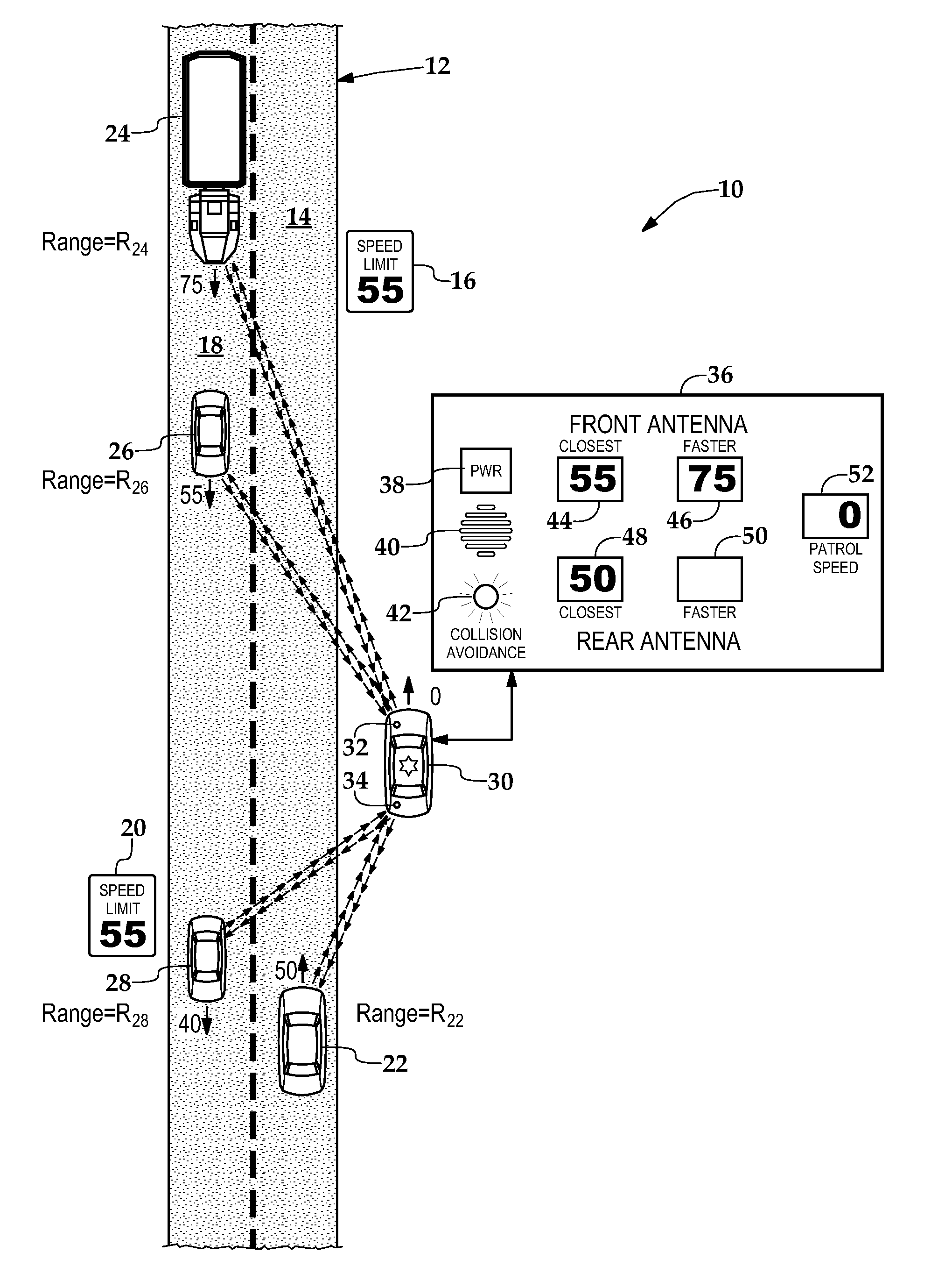
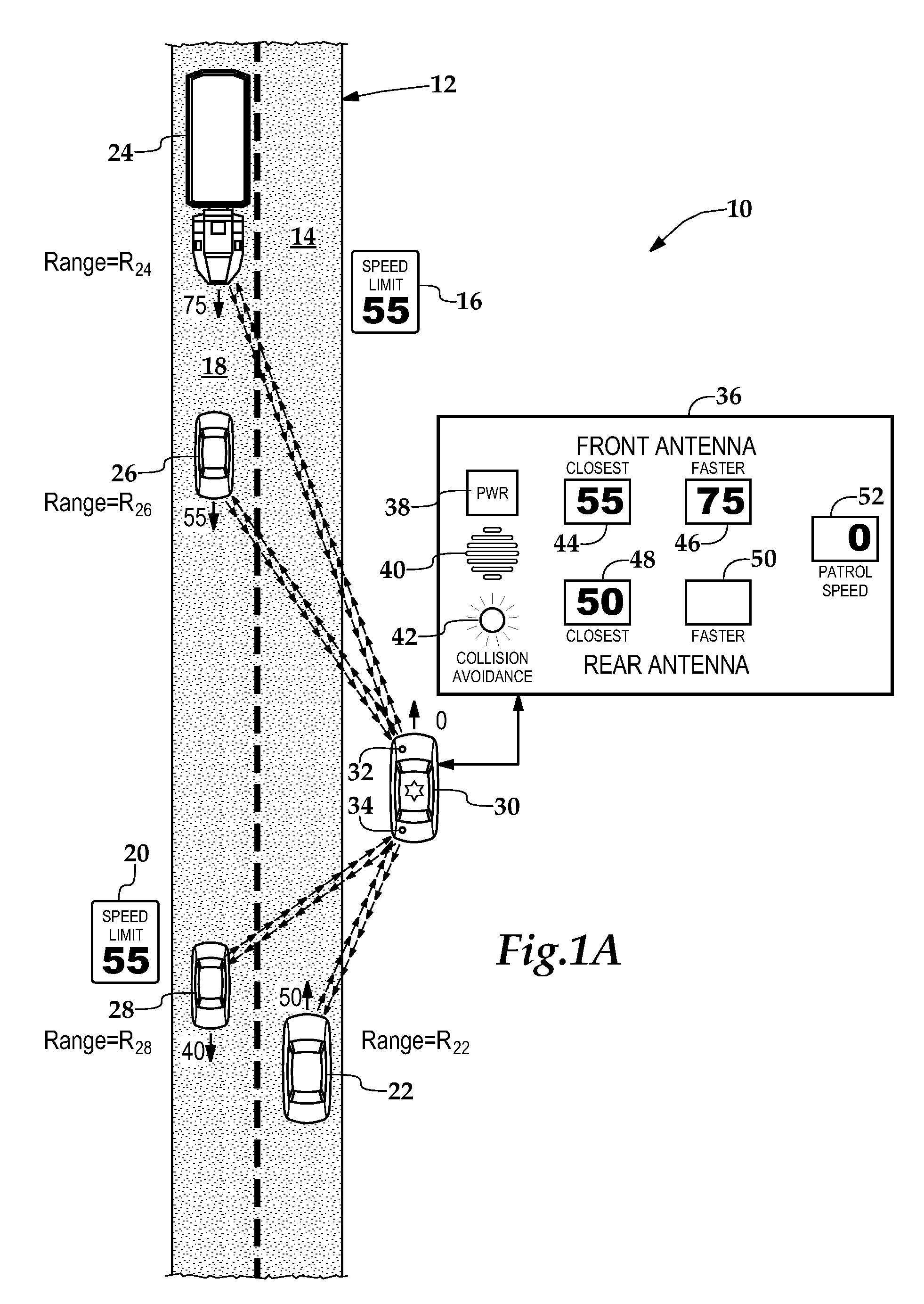
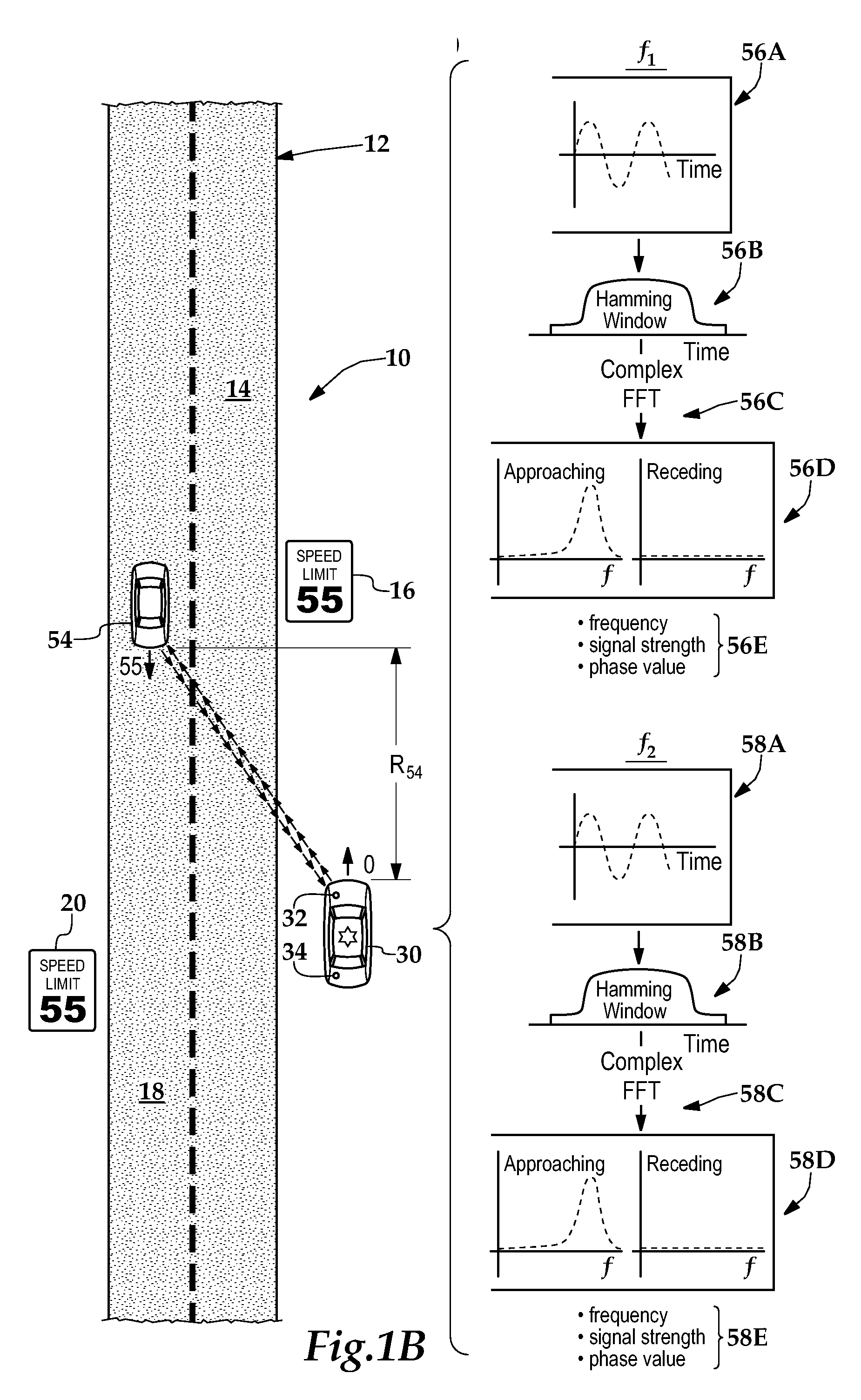
[0016] Referring initially to FIG. 1A, therein is depicted an environment 10 having multiple vehicles wherein one embodiment of the vehicular traffic surveillance Doppler radar system is being utilized. A highway 12 includes a northbound lane 14 having a speed limit of 55 mph as depicted by speed limit sign 16 and a southbound lane 18 having a speed limit of 55 mph as depicted by speed limit sign 20. A vehicle 22 is traveling in the northbound lane 14 at a speed of 50 mph as indicated by the northbound arrow and number “50” proximate to the front port...


PUM


Abstract

A vehicular traffic surveillance Doppler radar system and method for use of the same are disclosed. In one embodiment, the system comprises a modulation circuit portion for generating modulated FM signals. An antenna circuit portion transmits the modulated FM signals to a target and receives the reflected modulated FM signals therefrom. A ranging circuit portion performs a quadrature demodulation on the reflected modulated FM signals and determines a range measurement based upon phase angle measurements derived therefrom.

Description

CROSS-REFERENCE TO RELATED APPLICATIONS [0001] This application is a continuation of co-pending United States patent application Ser. No. 11 / 059,476, entitled “Vehicular Traffic Surveillance Doppler Radar System” and filed on Feb. 16, 2005, in the name of John L. Aker; which is hereby incorporated by reference for all purposes. This application discloses subject matter related to the subject matter disclosed in the following commonly owned, co-pending patent applications: (1) “Modulation Circuit for a Vehicular Traffic Surveillance Doppler Radar System,” filed on Feb. 16, 2005, application Ser. No. 11 / 059,199, in the name of John L. Aker; and (2) “System and Method for Calibrating a Vehicular Traffic Surveillance Doppler Radar,” filed on Feb. 16, 2005, application Ser. No. 11 / 059,474, in the name of John L. Aker; both of which are hereby incorporated by reference for all purposes. TECHNICAL FIELD OF THE INVENTION [0002] This invention relates, in general, to police radar systems and...

Claims


Application Information

Patent Timeline
Patent Type & Authority Applications(United States)
IPC IPC(8): G01S13/93G01S13/58
CPCG01S13/583G01S13/87G01S13/92
Inventor AKER, JOHN L.
Owner APPLIED CONCEPTS
Why Eureka
Try Eureka