Sterilizable lower mandibular tooth extraction forceps

a lower mandibular and forcep technology, applied in the field of sterilizable lower mandibular tooth extraction forceps, to achieve the effect of improving sterilizability

Inactive Publication Date: 2006-08-17
NIKOLOV GEORGE
View PDF29 Cites 3 Cited by
  • Summary
  • Abstract
  • Description
  • Claims
  • Application Information

AI Technical Summary

Benefits of technology

[0010] From the foregoing, it is seen that it is a problem in the art to provide a device meeting the above requirements. According to the present invention, a device and process are provided which meets the aforementioned requirements and needs in the prior art. Specifically, the device according to the present invention provides a sterilizable lower mandibular tooth extraction forceps having critical features which improve sterilizability.
[0013] 1. No sharp edges. There are no sharp edges on any of the surfaces of the instrument according to the present invention. Thus, contributing to safety during use and easier visualization during cleaning as the human eye sees smoother contours easier than it does sharp and angular shapes.
[0014] 2. Small surface area and essentially rectangular cross section of male elements, other than for the rounded corners of the rectangular cross sectional shape, increasing the probability of steam access and hence sterilization. Male elements are all those elements which enter into a groove or aperture.
[0015] 3. Essentially rectangular cross sectional shape of female elements, other than for the rounded corners of the rectangular cross sectional shape, which is arguably the best shape for manual cleaning and visual inspection prior to sterilization. This is one of the key features, and when coupled with the sterilization brush which exactly fits into them, sterilization is enhanced. Female elements include grooves, and any portions which receive a male element.

Problems solved by technology

From the foregoing, it is seen that it is a problem in the art to provide a device meeting the above requirements.

Method used


Image

  • Sterilizable lower mandibular tooth extraction forceps
  • Sterilizable lower mandibular tooth extraction forceps
  • Sterilizable lower mandibular tooth extraction forceps

Examples


Embodiment Construction

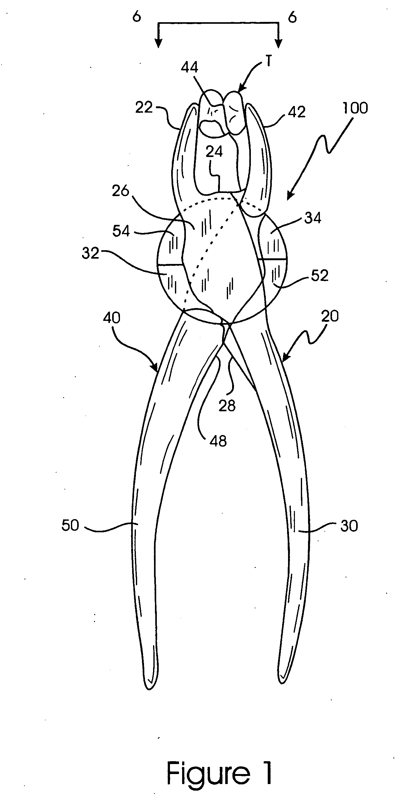
[0041] A sterilizable forceps 100, having critical features which improve sterilizability, is shown in FIG. 1 in an operational position clenching a tooth T between two beak elements 22 and 42. The sterilizable forceps 100 is composed of two parts, a first component 20 and a second component 40. The first component 20 and the second component 40 are preferably similar or even substantially identical to each other.

Critical Features of the Invention

[0042] The following features are deemed critical to the invention. While certain other features of the invention may be varied within the scope of the present invention as described elsewhere herein, the following features may not be departed from, as follows: [0043] a. No sharp edges. There are no sharp edges on any of the surfaces of the instrument according to the present invention. Thus, contributing to safety during use and easier visualization during cleaning as the human eye sees smoother contours easier than it does sharp and an...


PUM


Abstract

A sterilizable sterilizable lower mandibular tooth extraction forceps having critical features which improve sterilizability is composed of two parts, a first component and a second component which are similar to each other. The first component includes a handle portion, an intermediate portion, and a beak element angled with respect to the long axis of the handle. The intermediate portion has a generally flat upper surface, and has two opposed semicircular processes. The intermediate portion also has two groove portions. The first component has an upper shoulder portion, and carries a stop element on the handle portion. The first and second components can be separated simply by opening the handle portions to a maximum extended position. In the closed position, the semicircular processes of each component are engaged in groove portions formed by the other component.

Description

CONTINUING DATA [0001] This application is a continuation-in-part of U.S. Ser. No. 10 / 630,755 filed on Jul. 31, 2003, entitled “STERILIZABLE LOWER MANDIBULAR TOOTH EXTRACTION FORCEPS”, still pending, and is also a continuation-in-part of U.S. Ser. No. 10 / 370,769 filed on Feb. 24, 2003, entitled “STERILIZABLE DENTAL AND SURGICAL INSTRUMENT”, still pending.FIELD OF THE INVENTION [0002] The present invention relates to a sterilizable lower mandibular tooth extraction forceps having critical features which improve sterilizability. More particularly, the present invention relates to a sterilizable lower mandibular tooth extraction forceps having only two, manually separable components and having no connecting pin or hinge. BACKGROUND OF THE INVENTION [0003] Dental and surgical forceps and scissors are known in the prior art. Such prior art devices employ two opposing members connected by a hinge. Such hinges are typically made using a screw element or pin. [0004] Examples of known device...

Claims


Application Information

Patent Timeline
Patent Type & Authority Applications(United States)
IPC IPC(8): A61C3/14
CPCA61C3/14
Inventor NIKOLOV, GEORGE
Owner NIKOLOV GEORGE
Why Eureka
Try Eureka