
Method, apparatus, and computer program product for synchronizing triggering of multiple hardware trace facilities using an existing system bus

a technology of hardware trace facilities and system bus, applied in the field of data processing systems, can solve the problems of limiting the opportunity to collect characterization data from them, taking years to grow the initial system architecture draft, and never simple tradeoffs in the design of commercial server systems

Inactive Publication Date: 2006-08-17
IBM CORP
View PDF18 Cites 30 Cited by
  • Summary
  • Abstract
  • Description
  • Claims
  • Application Information

AI Technical Summary

Benefits of technology

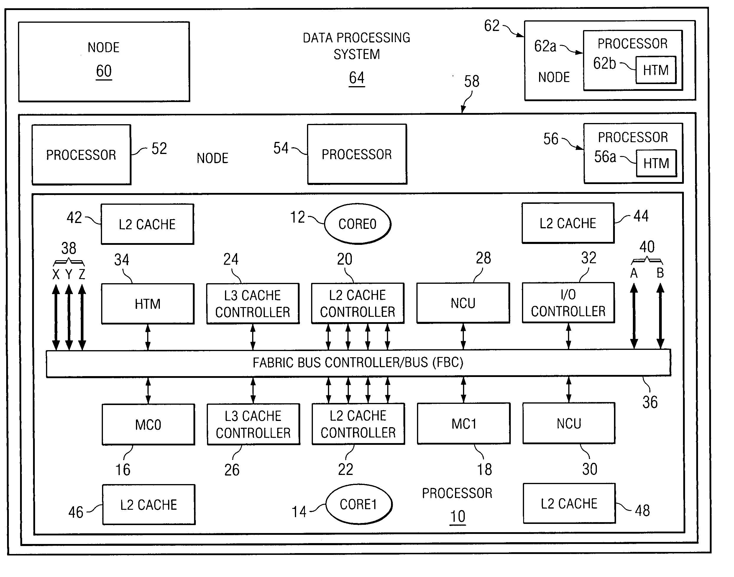
[0019] In addition, the tracing in the multiple hardware trace facilities can be synchronized by configuring one or more hardware trace facilities to be the masters. Other hardware trace facilities can be configured to be slaves. In this case, the master hardware trace facility will transmit the trace events that occur locally within the master's processor to the slave hardware trace facilities using the standard system bus and standard bus protocol. All of the hardware trace facilities, including the master and all slaves, will receive these events from the bus during a fixed number of bus clock cycle and be triggered by these events simultaneously.

Problems solved by technology

Making tradeoffs in the design of commercial server systems has never been simple.
For large commercial systems, it may take years to grow the initial system architecture draft into the system that is ultimately shipped to the customer.
Servers in general and commercial servers in particular place a large demand on system and operator resources, so the opportunities to collect characterization data from them are limited.
As computer systems migrate towards the use of sophisticated multi-stage pipelines and large SMP with SMT based systems, the ability to debug, analyze, and verify the actual hardware becomes increasingly more difficult, during development, test, and during normal operations.
For example, the developers are faced with the vexing problem of determining the origin of some rather long lock acquisition sequences in a multiprocessor system.
Moreover there is a need to have more than one trace facility simultaneously collecting different parts from the bus trace to reduce the chance of losing trace record because one trace facility alone can not handle the bus trace bandwidth.

Method used


Image

  • Method, apparatus, and computer program product for synchronizing triggering of multiple hardware trace facilities using an existing system bus
  • Method, apparatus, and computer program product for synchronizing triggering of multiple hardware trace facilities using an existing system bus
  • Method, apparatus, and computer program product for synchronizing triggering of multiple hardware trace facilities using an existing system bus

Examples


Embodiment Construction

[0028] A preferred embodiment of the present invention and its advantages are better understood by referring to the figures, like numerals being used for like and corresponding parts of the accompanying figures.

[0029] The present invention is a method, apparatus, and computer program product for synchronizing the triggering of multiple hardware trace facilities using an existing system bus.

[0030] There is need to have a global triggering mechanism that can be used to synchronize simultaneous collection of different traces. One trace facility is set up to collect a core trace and another is set up to record a fabric trace. Synchronization will be accomplished through the use of the global triggering mechanism. The software path for a long-delayed lock acquisition is “seeded” with the stop trigger command instruction. The trace collection buffers are configured to fill half the memory after receiving a stop trigger command. This effectively centers both traces on the long-delayed lo...


PUM


Abstract

A method, apparatus, and computer program product are disclosed in a data processing system for synchronizing the triggering of multiple hardware trace facilities using an existing bus. The multiple hardware trace facilities include a first hardware trace facility and a second hardware trace facility. The data processing system includes a first processor that includes the first hardware trace facility and first processing units that are coupled together utilizing the system bus, and a second processor that includes the second hardware trace facility and second processing units that are coupled together utilizing the system bus. Information is transmitted among the first and second processing units utilizing the system bus when the processors are in a normal, non-tracing mode, where the information is formatted according to a standard system bus protocol. Trigger events are transmitted to the hardware trace facilities utilizing the same standard system bus, where the trigger events are also formatted according to the standard system bus protocol.

Description

CROSS-REFERENCE TO RELATED APPLICATIONS [0001] The subject matter of the present application is related to copending U.S. applications, Ser. No. ______ [docket AUS920040992US1], titled “Method, Apparatus, and Computer Program Product in a Processor for Performing In-Memory Tracing Using Existing Communication Paths”, Ser. N. ______ [docket AUS920040993US1], titled “Method, Apparatus, and Computer Program Product in a Processor for Concurrently Sharing a Memory Controller Among a Tracing Process and Non-Tracing Processes Using a Programmable Variable Number of Shared Memory Write Buffers”, Ser. N. ______ [docket AUS920040994US1], titled “Method, Apparatus, and Computer Program Product in a Processor for Dynamically During Runtime Allocating Memory for In-Memory Hardware Tracing”, and Ser. N. ______ [docket AUS920041001US1], titled “Method, Apparatus, and Computer Program Product in a Processor for Balancing Hardware Trace Collection Among Different Hardware Trace Facilities”, all fil...

Claims


Application Information

Patent Timeline
Patent Type & Authority Applications(United States)
IPC IPC(8): G06F11/00
CPCG06F11/2268G06F11/348
Inventor AL-OMARI, RA'ED MOHAMMADFLOYD, MICHAEL STEPHENLECOCQ, PAUL FRANK
Owner IBM CORP
Learn More