Suction brush having UV sterilizing lamp for vacuum cleaner and a method for manufacturing the same

Inactive Publication Date: 2006-08-24
SAMSUNG GWANGJU ELECTRONICS CO LTD
View PDF3 Cites 16 Cited by
  • Summary
  • Abstract
  • Description
  • Claims
  • Application Information

AI Technical Summary

Benefits of technology

[0009] An aspect of the present invention is to solve at least the above problems and/or disadvantages and to provide at least the advantages described below. Accordingly, an aspect of the present inventio

Problems solved by technology

However, when any obstacle exists on a path of a UV ray projected from the UV sterilizer lamp, the UV ray is not able to pass through the obstacle.
When the UV sterilizer lamp is exposed as the above, however, the dust being collected may contaminate or damage the UV sterilizer lamp as time elapses.
Especially, when a surface of the UV sterilizer lamp is polluted, the UV ray, being blocked by the dust attached on the surfac

Method used


Image

  • Suction brush having UV sterilizing lamp for vacuum cleaner and a method for manufacturing the same
  • Suction brush having UV sterilizing lamp for vacuum cleaner and a method for manufacturing the same
  • Suction brush having UV sterilizing lamp for vacuum cleaner and a method for manufacturing the same

Examples


first embodiment

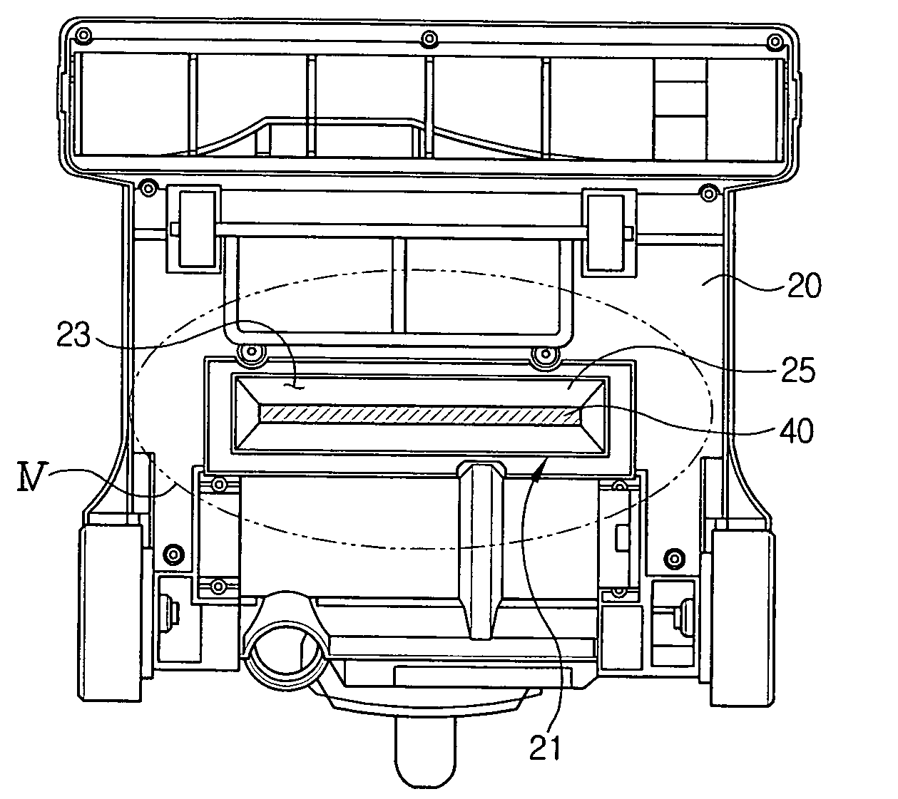
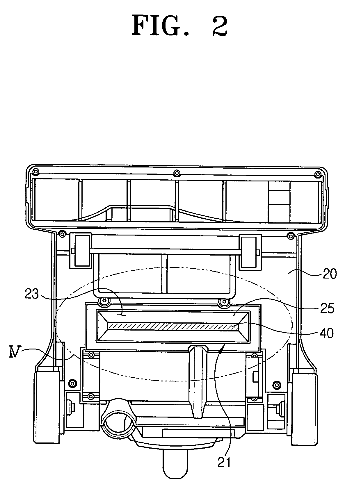
[0029] According to the present invention, as shown in FIGS. 3 and 4, a specular surface 25 is formed in the inner space 23 to focus the generated UV ray upon the surface being cleaned. The specular surface 25 is formed to widen toward the surface being cleaned so as to converge the UV ray generated in the UV sterilizer lamp 40 as much as possible and then evenly distribute the converged UV ray onto the surface being cleaned. The specular surface 25 is made of a material having superior reflexibility. Therefore, the specular surface 25 may be implemented by attaching an aluminum tape on a wall of the inner space 23.

[0030] A transparent TEFLON window member 50 is connected to the opening 21 at a predetermined distance ‘g’ from the opening 21 in order to prevent the UV sterilizer lamp 40 mounted at the inner space 23 from being contaminated by the drawn-in dust. Since the TEFLON has superior transmittance, the TEFLON window member 50 does not have to be transparent. However, for a use...

second embodiment

[0038] Although not explained in detail, in the second embodiment as well, ends of the connection projections 22b as penetrating the connection holes 51 are compressed by heat and pressure to thereby fix the TEFLON window member 50 at the determined position.

[0039] Using the transparent TEFLON window member 50 as described above, robustness against impact can be improved compared to the conventional art using a quartz glass for the window member. In addition, since the TEFLON window member 50 protecting the UV sterilizer lamp 40 from dust or obstacles is connected to the opening 21 mounting therein the UV sterilizer lamp 40 in a ventilative manner, the inner space 23 including the UV sterilizer lamp 40 is not completely sealed. Therefore, the heat generated by the UV sterilizer lamp 40 can be discharged to the outside, thereby preventing malfunction of the UV sterilizer lamp 40 due to the high temperature.

[0040] Furthermore, by forming the window member of the transparent TEFLON re...


PUM


Abstract

A suction brush and a method for manufacturing the same are provided. The suction brush includes an opening formed toward a surface being cleaned, the UV sterilizer lamp is mounted at an inner space of the opening to project a UV ray onto the surface, and a TEFLON window member covering the inner space. The method includes mounting the UV sterilizer lamp at an inner space of an opening formed toward a surface being cleaned, connecting a TEFLON window member by fitting a plurality of connection projections formed around the opening into a plurality of connection holes formed at the TEFLON window member to correspond to the connection projections, determining a connection position for the TEFLON window member so that the inner space is ventilative, and fixing the TEFLON window member by compressing ends of the plurality of connection projections as penetrating the connection holes by heat and pressure.

Description

CROSS-REFERENCE TO RELATED APPLICATIONS [0001] This application claims benefit under 35 U.S.C. § 119(a) of Korean Patent Application No. 2005-15068, filed Feb. 23, 2005, the entire contents of which are incorporated herein by reference. BACKGROUND OF THE INVENTION [0002] 1. Field of the Invention [0003] The present invention relates to a vacuum cleaner. More particularly, the present invention relates to a vacuum cleaner suction brush having an ultraviolet (UV) sterilizer for disinfecting a surface being cleaned, and a method for manufacturing the same. [0004] 2. Description of the Related Art [0005] Generally, a vacuum cleaner collects dust on a surface being cleaned by drawing in ambient air, using a negative pressure generated by a vacuum suction means mounted in a cleaner body. With the booming of well-being and healthy life-styles, recently, a vacuum cleaner having an ultraviolet (UV) sterilizer provided to the cleaner body has been introduced in order to remove germs which may...

Claims


Application Information

Patent Timeline
IPC IPC(8): A47L5/00
CPCA47L9/02A61L2/10A47L7/04
Inventor LEE, HAK-BONGOH, JANG-KEUNSEO, JI-WON
Owner SAMSUNG GWANGJU ELECTRONICS CO LTD
Why Eureka
Try Eureka