Wrapping device

a wrapping device and a technology for wrapping, applied in the direction of packaging, packaging, transportation and packaging, etc., can solve the problems of affecting the handling of the lift truck, the holding arm and the wrapping arm are interfering, and the pallet must be repeatedly picked up by the lift truck, so as to ensure the stability of the wrapping device during operation, ensure the stability of the wrapping device, and facilitate the separation

Inactive Publication Date: 2006-08-24
PREMARK PACKAGING LLC
View PDF13 Cites 2 Cited by
  • Summary
  • Abstract
  • Description
  • Claims
  • Application Information

AI Technical Summary

Benefits of technology

[0007] The wrapping device according to the invention comprises a base body containing, for example, control units and the like. The base body has connected thereto a holding arm which is preferably of L-shaped configuration and comprises substantially vertically and horizontally aligned portions. The holding arm, in particular the horizontal arm, has rotatably connected thereto a wrapping arm for wrapping-up in particular objects arranged on a pallet. According to the invention, the base body is connected to a fastening element. The fastening element serves for fastening the inventive wrapping device to support elements of a lift truck, said support elements normally being of fork-shaped configuration. It is thus possible to fasten the inventive wrapping device with the aid of the fastening elements to the support elements and / or the fork-like portions of a conventional lift truck. It is thus possible to provide a mobile wrapping device by fastening the wrapping device to the lift truck, with the aid of which mobile wrapping device e. g. pallets can be transported and wrapped up. Thus placing the pallet e. g. on a turntable of a stationary wrapping device is no longer necessary. Further, the invention offers the advantage that the wrapping device can be easily separated from the lift truck such that the lift truck can be used for normal transport etc. of pallets, wherein the functionality and the application of the lift truck are not affected by the wrapping device.
[0008] The fastening elements are preferably configured such that the wrapping device can be quickly and easily connected with and separated from the lift truck. In this connection it is particularly preferred that the fastening elements comprise recesses into which the support elements of the lift truck can be inserted. It is particularly preferred that the fastening elements are configured such that they at least partially embrace the support elements of the lift truck. It is thus possible to insert the support elements, such as the cables of the lift truck, into the recesses and in this simple manner to connect the inventive wrapping device with the lift truck. By simply pulling the support elements out of the recesses the wrapping device can be separated from the lift truck. Thus laborious installation work is not required. Rather, the fastening elements are preferably connected to the support elements by inserting or pulling out the fastening elements.
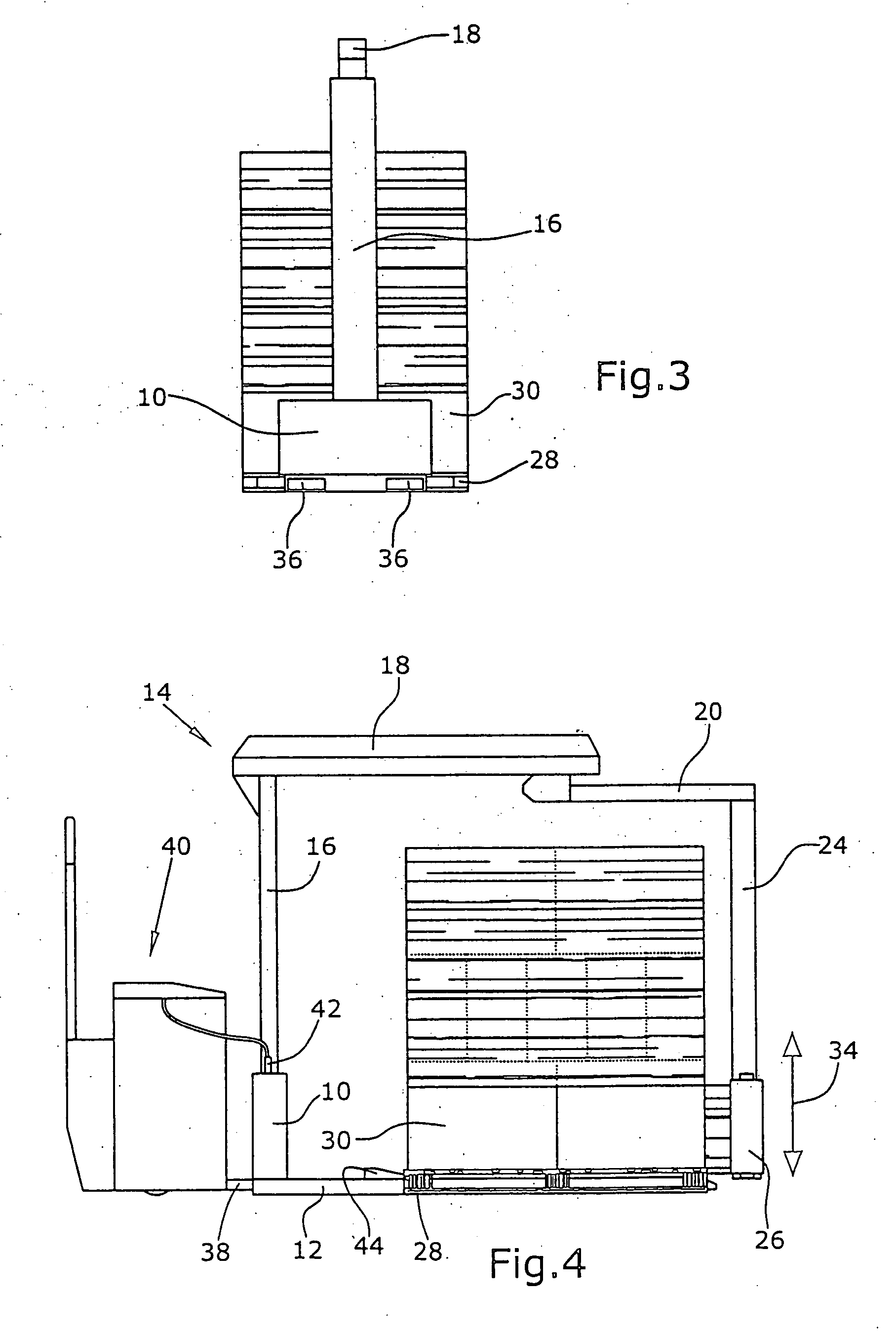
[0009] In a particularly preferred embodiment, the fastening elements of the wrapping device have substantially the same shape as the support elements of the lift truck. Such fastening elements are thus, for example, configured as a hollow fork-like portion into which the support elements and / or the fork-like portion of the lift truck can be inserted. The support elements of the lift truck are then preferably completely encompassed by the fastening elements. The fastening elements are thus configured as a hollow lift truck fork, wherein the individual fastening elements are preferably connected with each other via a stabilizing cross web. The fastening elements configured as a hollow lift truck fork offer a footprint for the wrapping device, which is sufficient to ensure stability of the wrapping device during operation without necessitating any further assistance means and without the danger of an accidental tilt. This embodiment of the fastening elements offers the further advantage that the position of the wrapping device relative to the lift truck is easily defined, i. e. by simply inserting the support elements into the fastening elements. Further, this embodiment offers a stable connection between the wrapping device and the lift truck such that even relatively large lateral forces can act upon the wrapping device.
[0010] The wrapping device according to the invention may comprise its own power supply unit, for example in the form of chargeable batteries. For reducing the weight of the wrapping device, the wrapping device preferably comprises a power supply connection for connecting the wrapping device to an external power source. It is particularly preferred to connect the wrapping device to the power supply unit of the electric lift truck since this ensures a high mobility and allows pallets to be wrapped up independent of stationary power connections.
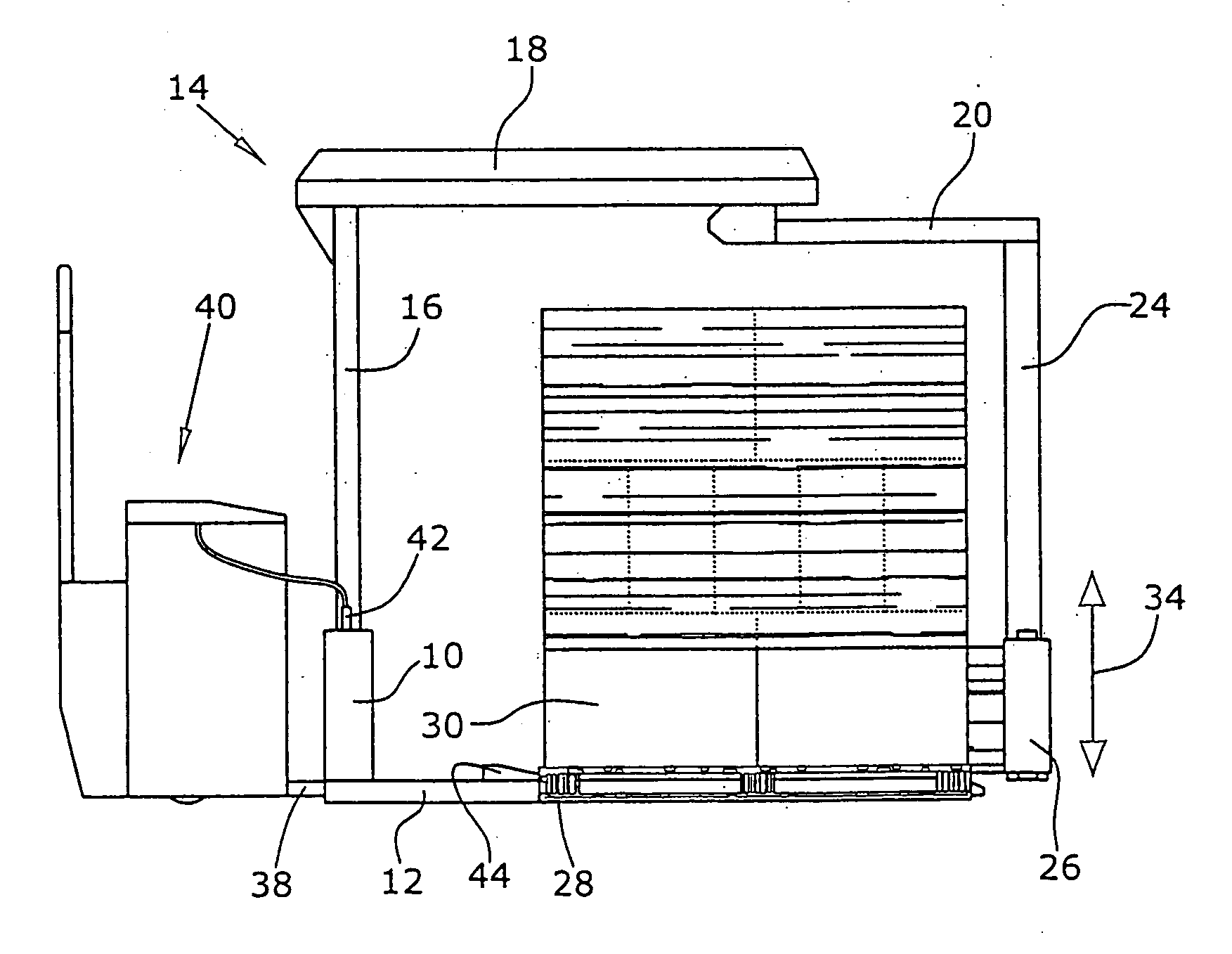
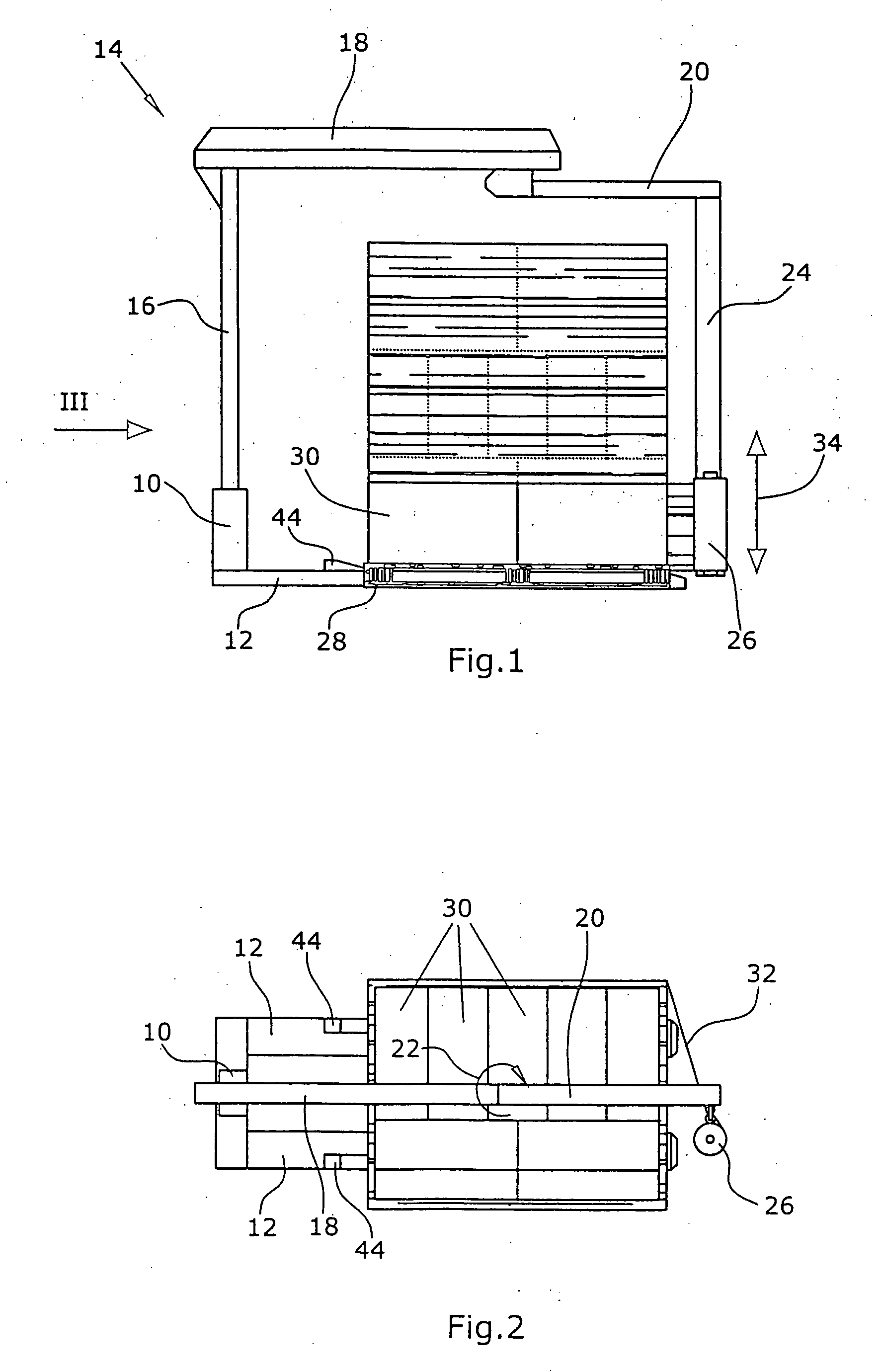
[0012] Provision of a stop element is an independent invention, wherein the stop element may be provided, for example, not only on the wrapping device described above but also on a wrapping device fixed to a lift truck, in particular on the support elements. Thus the invention further relates to a pallet stop element for accepting a pallet, wherein the pallet stop element is in particular suitable for the wrapping device described above or a lift truck. According to the invention, the support element comprises on its upper side the pallet stop element for defining the position of the pallet. The stop element, i. e. the pallet stop element, comprises a friction surface for frictionally engaged holding of the pallet, the friction surface being inclined relative to the horizontal and sloping towards pallet to be picked up. The stop element is, for example, at least partially of wedge-shaped configuration such that the friction surface is defined by the side surfaces of the wedge-shaped portion of the stop element. When the stop element according to the invention accepts the pallet, the wedge-shaped portion of the stop element slightly lifts the pallet, whereby a major portion of the weight of the pallet and the goods arranged on the pallet is gradually taken up the friction surface. Thereby a large friction force is produced which defines the position of the pallet. In contrast to an e. g. rectangular stop element, the inventive stop element prevents a sudden collision of the pallet with the stop element such that the danger of damage to the pallet and / or the goods is reduced. Further, the pallet is prevented from rebounding from the stop element and thus from experiencing a dislocation such that even in the case of uncareful use of the wrapping device and / or the lift truck with which the inventive pallet stop element is connected, a defined position of the pallet relative to the support element is ensured.

Problems solved by technology

Since this procedure is however extremely personnel—and thus cost-intensive, wrapping devices, i. e. automatically operating wrapping machines, are known.
The automatic wrapping-up of pallets with the aid of a wrapping device or a wrapping machine has thus the drawback that the pallet must be repeatedly picked up by the lift truck or another suitable transport means.
Such a lift truck with a wrapping device has however the drawback that in particular the holding arm and the wrapping arm are interfering when the lift truck is used in a normal manner, i. e. when pallets are transported which are not intended for being wrapped up.
In particular, it is always necessary to carry along a relatively large weight, which affects handling of the lift truck.
Further, in particular the horizontal portion of the holding arm is interfering since said portion limits the height to which objects can be stacked on the pallet.
The horizontal portion of the holding arm is, for example, also interfering when a pallet is placed into a rack or another difficult-to-access area.

Method used


Image

  • Wrapping device
  • Wrapping device
  • Wrapping device

Examples


Embodiment Construction

[0020] The wrapping device according to the invention comprises a base body 10 connected with two support elements 12, wherein the support elements 12 are configured in mutual parallel relationship and in the shape of a fork as in the case of a fork lift truck. The base body 10 has connected thereto an L-shaped holding arm 14. The holding arm 14 comprises a vertically arranged column-shaped portion 16 and a horizontally arranged arm 18. The arm 18 has connected thereto a wrapping arm 20 which is connected to rotate with the arm 18 in the direction indicated by arrow 22. The wrapping arm 20 has rigidly connected thereto a vertically extending roll holder 24. The roll holder 24 carries a film roll 26.

[0021] For wrapping-up objects 30 arranged on a pallet 28, the wrapping arm 20, together with the roll holder 24, is turned in the direction indicated by arrow 22 around the objects stacked one on top of the other. Thereby the film sheet 32 is wrapped around the objects 30 for fixing the...


PUM

PropertyMeasurementUnit
areaaaaaaaaaaa
wrapping areaaaaaaaaaaa
heightaaaaaaaaaa

Abstract

A wrapping device includes a base body which is connected with support elements and a holding arm. The holding arm has rotatably connected thereto a wrapping arm. The wrapping arm carries a roll holder. At the roll holders a rotatably supported film roll is arranged for being displaced in a predetermined direction for wrapping up objects arranged on a pallet. For transporting the wrapping device, the support elements serve as fastening elements and are of hollow configuration such that support elements of a lift truck can be inserted therein.

Description

RELATED APPLICATIONS [0001] The present application is a divisional application of U.S. patent application Ser. No. 10 / 867,211, filed Jun. 15, 2004, which claims benefit of German Application Serial No. 203 09 382.8, filed Jun. 16, 2003, the entire disclosures of which are hereby incorporated by reference.BACKGROUND OF THE INVENTION [0002] The invention relates to a wrapping device for wrapping-up objects, in particular pallets, with a film. [0003] For transporting e. g. objects stacked on pallets, such as cardboard boxes or the like, it is common practice to wrap up the pallet, together with the objects, with a film, in particular a prestretched film. This ensures safe hold of the objects on the pallet. Wrapping-up of pallets is frequently carried out by hand. Since this procedure is however extremely personnel—and thus cost-intensive, wrapping devices, i. e. automatically operating wrapping machines, are known. Said machines comprise a turntable on which the pallet to be wrapped u...

Claims


Application Information

Patent Timeline
Patent Type & Authority Applications(United States)
IPC IPC(8): B65B11/00B65B11/02B66F9/18
CPCB65B11/025B65B2210/20B66F9/18
Inventor HEIKAUS, GERD
Owner PREMARK PACKAGING LLC
Why Eureka
Try Eureka