Lift mechanism systems and methods

a technology of lifting mechanism and spring, which is applied in the direction of machine supports, furniture parts, variable height tables, etc., can solve the problems of not being able to place personal computers and/or display monitors, gas springs suitable for lifting mechanisms may cost about six dollars, etc., and achieves cost-effectiveness, high reliability, and low cost

Inactive Publication Date: 2006-08-24
ERGOTRON
View PDF11 Cites 98 Cited by
  • Summary
  • Abstract
  • Description
  • Claims
  • Application Information

AI Technical Summary

Benefits of technology

[0014] Embodiments of the invention may provide one or more of the following advantages. For example, embodiments of the invention may provide high reliability at a relatively low cost. Some embodiments may be manufactured and / or maintained in a more cost-effective manner than applications using, for example, electrical motors, hydraulic motors, or gas springs as their power source. To illustrate, some embodiments of the present invention may use a coil spring, and a coil spring suitable for use in the present invention may cost, for example, on the order of eighteen cents. In contrast, a gas spring suitable for use in lifting mechanisms may cost about six dollars. By way of another example involving coil spring embodiments, a lift providing support for an 80 pound load through 20 inches of travel using only about four dollars worth of coil springs. In contrast, a prior art lifting technology, capable of supporting a 70 pound load across sixteen inches of travel, may require, for example, two gas springs costing twenty-two dollars each.

Problems solved by technology

Some situations may not be conducive to placing personal computers and / or display monitors directly on a desk or on a computer case.
In contrast, a gas spring suitable for use in lifting mechanisms may cost about six dollars.

Method used


Image

  • Lift mechanism systems and methods
  • Lift mechanism systems and methods
  • Lift mechanism systems and methods

Examples


Embodiment Construction

[0059] The following detailed description should be read with reference to the drawings, in which like elements in different drawings are numbered identically. The drawings, which are not necessarily to scale, depict selected embodiments and are not intended to limit the scope of the invention. Examples of constructions, materials, dimensions, and manufacturing processes are provided for selected elements. All other elements employ that which is known to those of skill in the field of the invention. Those skilled in the art will recognize that many of the examples provided have suitable alternatives that can be utilized.

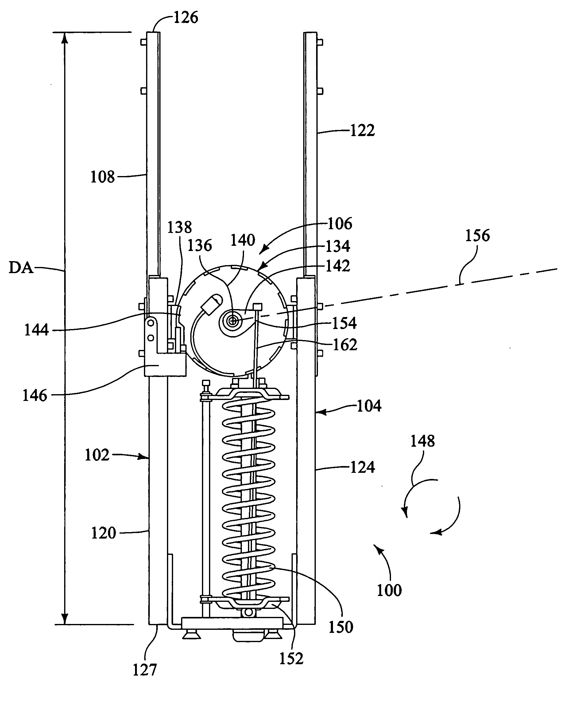
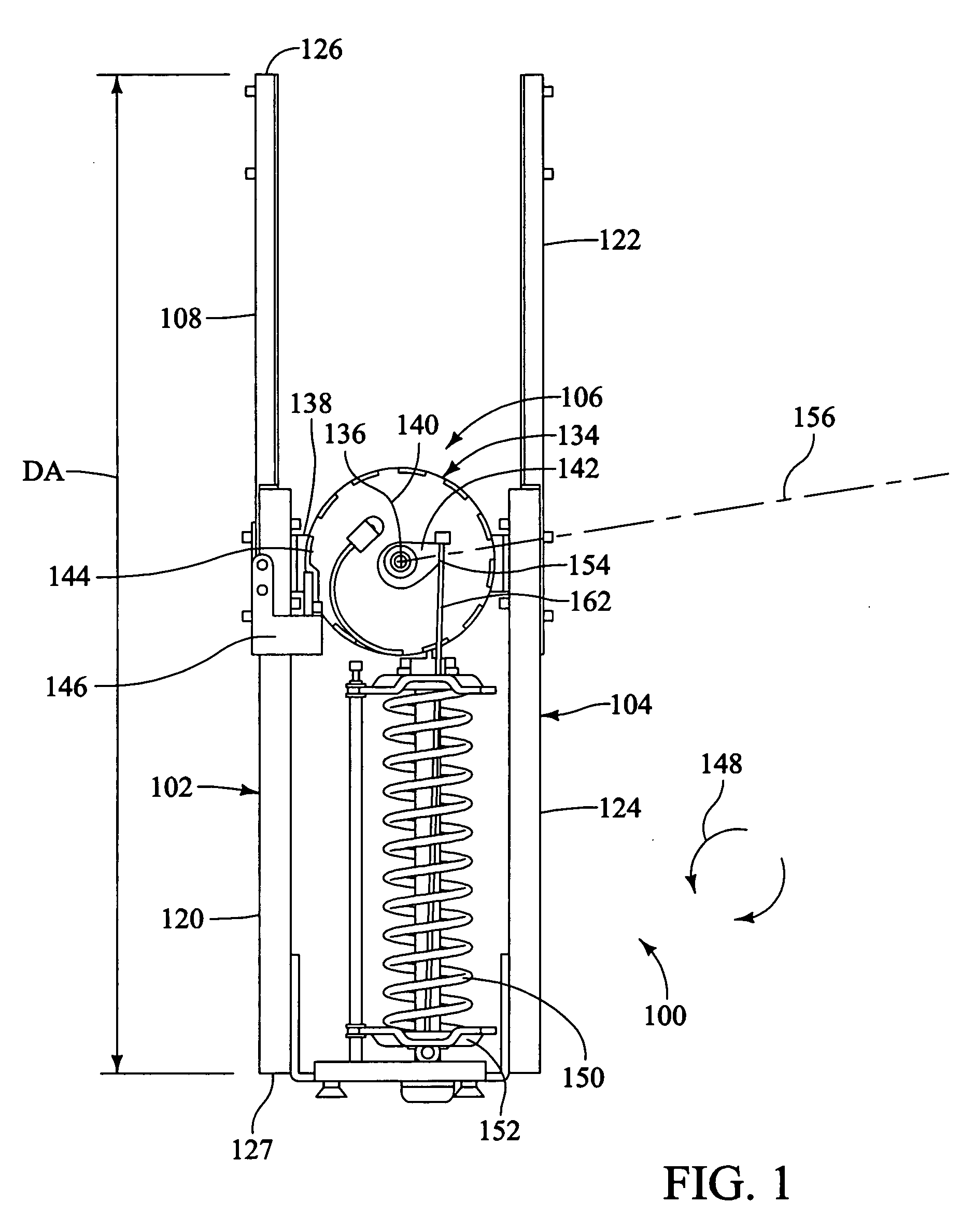
[0060]FIG. 1 is an elevation view of an apparatus 100 in accordance with an exemplary embodiment of the present invention. Apparatus 100 of FIG. 1 comprises a first slide 102, a second slide 104 and a balance mechanism 106. First slide 102 comprises a first inner rail 108 and a first outer rail 120 that are disposed in sliding engagement with one another. In the emb...


PUM


Abstract

The invention includes a display positioning assembly comprising a support, a display supported by the support, and a balance mechanism carried by the display and operatively connected to the support. The invention also includes an article for selectively exposing a display comprising a generally planar support surface having a first side and a second side opposite the first side. A balance mechanism operatively connected to a display may be positionable between a storage position proximate the first side of the generally planar support surface and an exposed position proximate the second side of the generally planar support surface. The invention also includes an assembly for arresting the free fall of an object. The assembly may comprise an outer slide in sliding or rolling engagement with an inner slide, and a brake comprising at least one pivot member may be coupled to the inner slide.

Description

RELATED APPLICATIONS [0001] The present application is a continuation in part of U.S. application Ser. No. 10 / 903,316, filed on Jul. 30, 2004. [0002] The present Application claims the benefit of U.S. Provisional Patent Application Ser. No. 60 / 613,993, filed on Sep. 28, 2004. [0003] The present Application claims the benefit of U.S. Provisional Patent Application Ser. No. 60 / 633,999, filed on Dec. 7, 2004. [0004] The entire disclosure of each of the above-mentioned patent applications is hereby incorporated by reference herein.FIELD OF THE INVENTION [0005] The present invention relates generally to an apparatus for supporting a load or for supplying a pre-determined force either constant or variable in either a vertical or horizontal or other orientation. BACKGROUND OF THE INVENTION [0006] In recent years, ergonomic concerns have taken on increased importance due to several factors. For example, workers are often able to be more productive when working in an ergonomically friendly e...

Claims


Application Information

Patent Timeline
Patent Type & Authority Applications(United States)
IPC IPC(8): A47B37/00F16M11/20
CPCA47B21/0073F16M11/04F16M11/10F16M11/18F16M11/24F16M11/30F16M13/02F16M2200/044F16M2200/048A47B9/02A47B9/12A47B9/20A47B2200/0076F16M11/046F16M11/2021F16M2200/041F16M2200/047A47B81/064F16M11/28F16M11/42H01H85/24
Inventor SWEERE, HARRY C.ERGUN, MUSTAFA A.FLUHRER, ROBERT W.LINDBLAD, SHAUN C.ELIASON, JEFFREY M.NISTLER, STEVESALTZ, RONFUNK, JOE
Owner ERGOTRON
Why Eureka
Try Eureka