Pressure relief valve with debris trap

a technology of debris trap and pressure relief valve, which is applied in the direction of mechanical equipment, transportation and packaging, functional valve types, etc. it can solve the problems of insufficient output pressure and/or volume of the pump at lower operating speeds, chamfers tend to increase the likelihood of debris being caught, and suffer from disadvantages. , to achieve the effect of enhancing the retention of magnetic debris particles and enhancing the capture of debris particles

Inactive Publication Date: 2006-08-24
MAGNA POWERTAIN
View PDF23 Cites 12 Cited by
  • Summary
  • Abstract
  • Description
  • Claims
  • Application Information

AI Technical Summary

Benefits of technology

[0012] Preferably, the recess includes a chamfered upper inner edge to enhance capture of debris particles in the recess. Also preferably, the recess is magnetized, or includes a magnetic member, to enhance the retention of magnetic debris particles within the recess.

Problems solved by technology

While such pressure relief valves are quite simple in operation and construction, they do suffer from disadvantages.
In particular, debris entrained in the working fluid can jam the plunger by being caught between the corner of the upper surface of the plunger and the corner of the waste passage, preventing it from returning to its closed position as the output pressure of the pump is reduced and this can result in the pump producing an insufficient output pressure and / or volume at lower operating speeds.
This chamfer tends to increase the likelihood that debris will be caught between the corner of the plunger and the corner of the waste passage.
While, in some circumstances, flow-through plungers are somewhat less likely to be jammed by debris than conventional plungers, it has been determined that flow-through plungers can still be jammed by debris.
Also, flow-through plungers typically require the overall length of the valve and bore to be greater than non-flow-through designs and it is often not possible to design a pump which can provide the necessary length.
Further, flow through plungers are more expensive to manufacture, due to the additional machining steps required for their manufacture.
In view of the above, and as flow-through plungers do not significantly reduce the chances of jamming, it is believed that they do not offer a worthwhile solution to this problem.

Method used


Image

  • Pressure relief valve with debris trap
  • Pressure relief valve with debris trap
  • Pressure relief valve with debris trap

Examples


Embodiment Construction

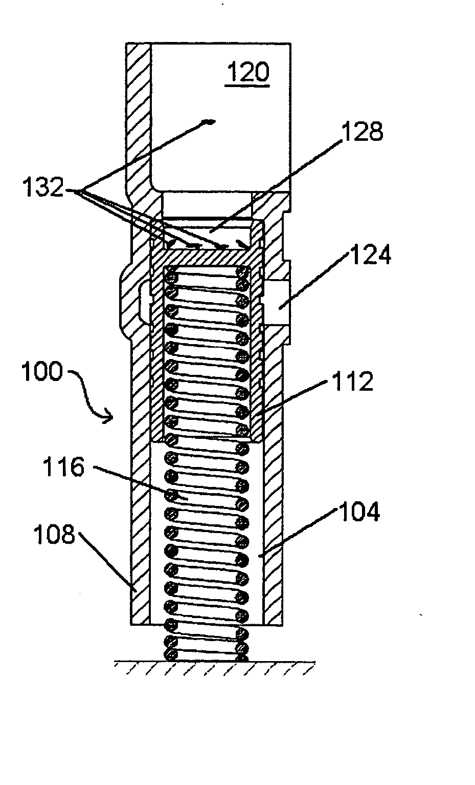
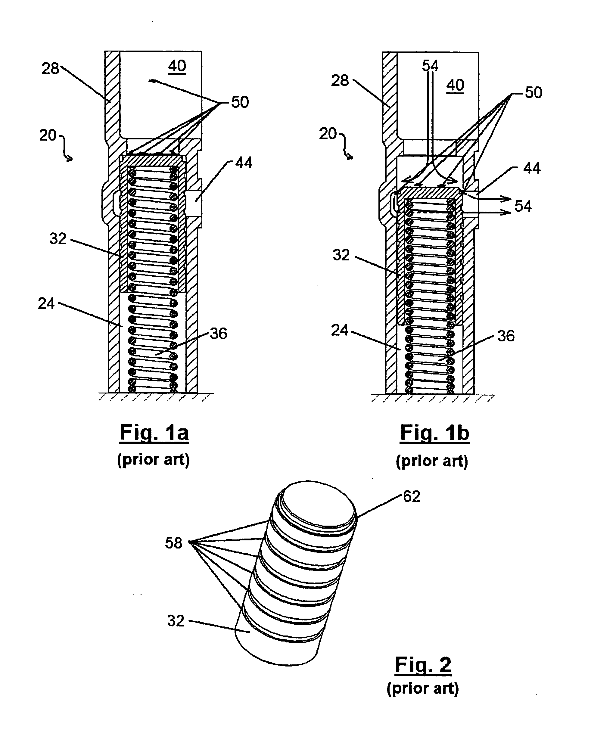
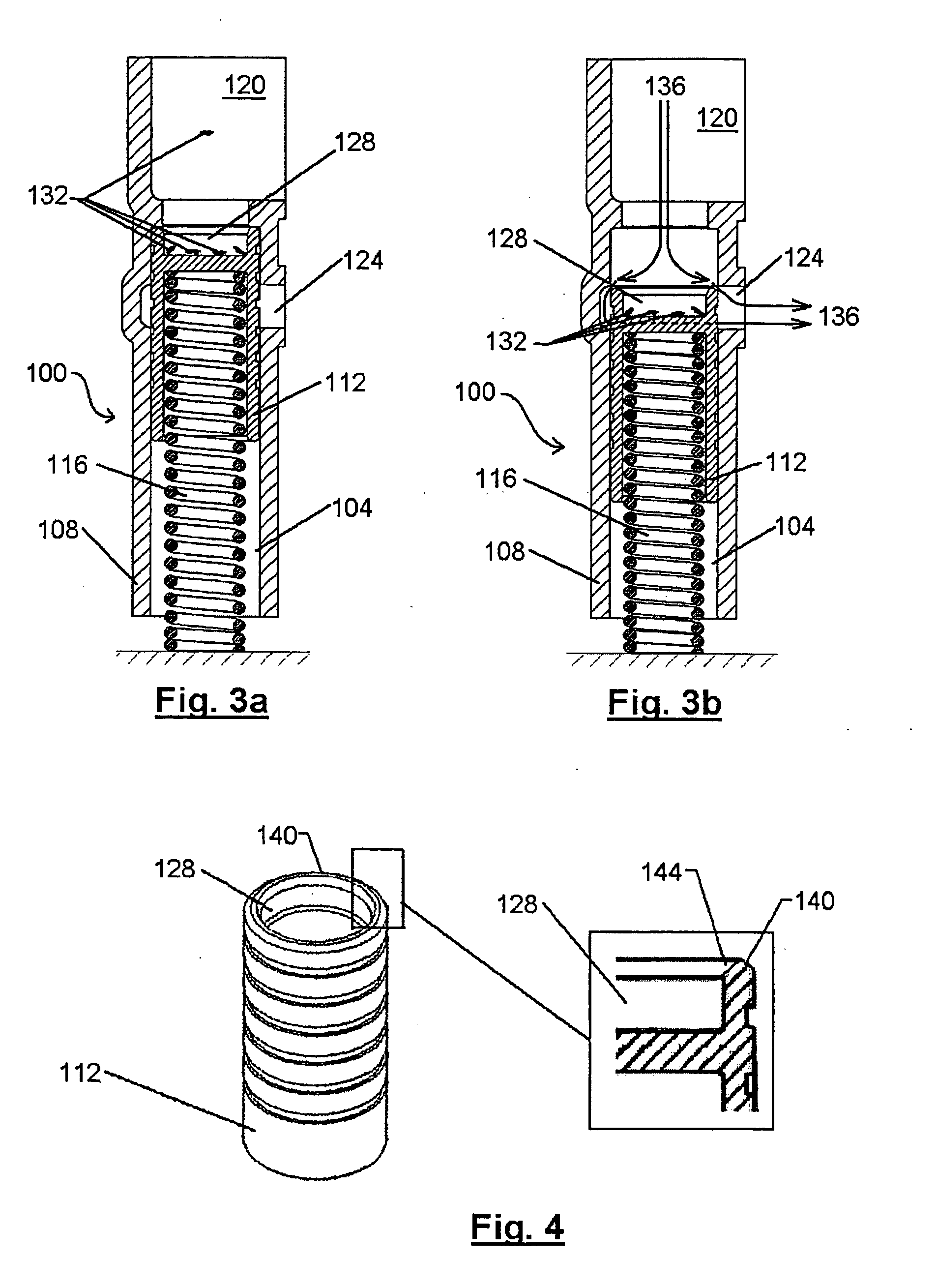
[0018] A prior art pressure relief valve is indicated generally at 20 in FIGS. 1a and 1b. As shown, valve 20 comprises a bore 24, typically in the housing 28 of the pump, in which a plunger 32 and a biasing spring 36 are arranged. A plug, such as a bolt or screw (not shown), is located at the end of bore 24 distal plunger 32 to seal bore 24 and biasing spring 36 acts between plunger 32 and this plug or insert. In some other embodiments of valve 20, the plug is located at the other end of bore 24, adjacent a passage that connects that end of bore 24 to the high pressure area of the pump, and biasing spring 36 acts between plunger 32 and the opposite, blind, end of bore 24.

[0019] Area 40 in the Figures is in fluid communication with the high pressure side of the pump and waste passage 44 is in fluid communication with a low pressure area, such as the low pressure side of the pump, or a low pressure gallery, etc.

[0020] In FIG. 1a, the pressure of the working fluid in area 40 is insuf...


PUM


Abstract

A pressure relief valve for a pump includes a recess in its surface adjacent the high pressure side of the pump. The recess acts as a trap to capture and retain debris particles in the working fluid. By capturing and retaining the debris particles in the recess, jamming of the pressure relief valve in an open position can be avoided. Preferably, the upper edge of the recess includes a chamfered edge which enhances the likelihood of the debris particles entering the recess. Also preferably, the recess can be magnetized, or a magnetic member can be inserted into the recess, to enhance the capture and retention of magnetic debris particles in the recess.

Description

CROSS-REFERENCE TO RELATED APPLICATIONS [0001] This application claims the benefit of U.S. Provisional Application No. 60 / 646,760, filed on Jan. 24, 2005. The disclosure of the above application is incorporated herein by reference.FIELD OF THE INVENTION [0002] The present invention relates to pressure relief valves for pumps. More specifically, the present invention relates to pressure relief valves for pumps wherein the valve has a trap to retain debris to prevent the debris from jamming the valve. BACKGROUND OF THE INVENTION [0003] Many pumps, such as oil pumps in automotive engines, include a pressure relief valve to limit the output of the pump to establish an equilibrium operating pressure for the pump which is intended to be largely independent of changes in the operating speed of the pump. [0004] In many cases, these pressure relief valves are quite simple in design and comprise a bucket-like plunger in a bore within the pump, the bore being in fluid communication with the hi...

Claims


Application Information

Patent Timeline
Patent Type & Authority Applications(United States)
IPC IPC(8): F16K15/00
CPCF16K17/0426Y10T137/7925
Inventor WILLIAMSON, MATTHEWHODGES, PAUL M.
Owner MAGNA POWERTAIN
Why Eureka
Try Eureka