
Method of locating liner within sewer pipe

Active Publication Date: 2006-08-24
LMK TECH LLC
View PDF20 Cites 8 Cited by
  • Summary
  • Abstract
  • Description
  • Claims
  • Application Information

AI Technical Summary

Benefits of technology

[0007] It is therefore a general object, feature, or advantage of the present invention to improve upon the state of the art.
[0008] Another object, feature, or advantage of the present invention is to provide a single access bore for inverting a lateral liner into a pipe to be repaired.
[0009] Yet another object, feature, or advantage of the present invention is to provide a method for installing and positioning a liner within a sewer pipe that does not block off the sewer pipe.
[0010] A further object, feature, or advantage of the present invention is to provide an inversion method for installing a lateral liner through a clean out that does not require cutting out the liner to reinstate service to a house.
[0011] A still further object, feature, or advantage of the present invention is to provide an inversion method for installing a lateral liner through a clean out that does not involve a cutting or reinstating process requiring expensive equipment.
[0012] Another object, feature, or advantage of the present invention is to provide an inversion method for installing a lateral liner through a clean out that does not require additional time for a reinstating process or cutting.

Problems solved by technology

If the lining does not have an outer coating, the resin impregnated into the lining may be contaminated and even wiped off during the pulling in process.
However, it is often undesirable to require two separate access points and it would generally be considered advantageous to require only one access point.
This type of reinstating process requires expensive equipment, requires additional time and if the cut is not smooth, solids will build up on the lining, causing backups.

Method used


Image

  • Method of locating liner within sewer pipe
  • Method of locating liner within sewer pipe
  • Method of locating liner within sewer pipe

Examples


Embodiment Construction

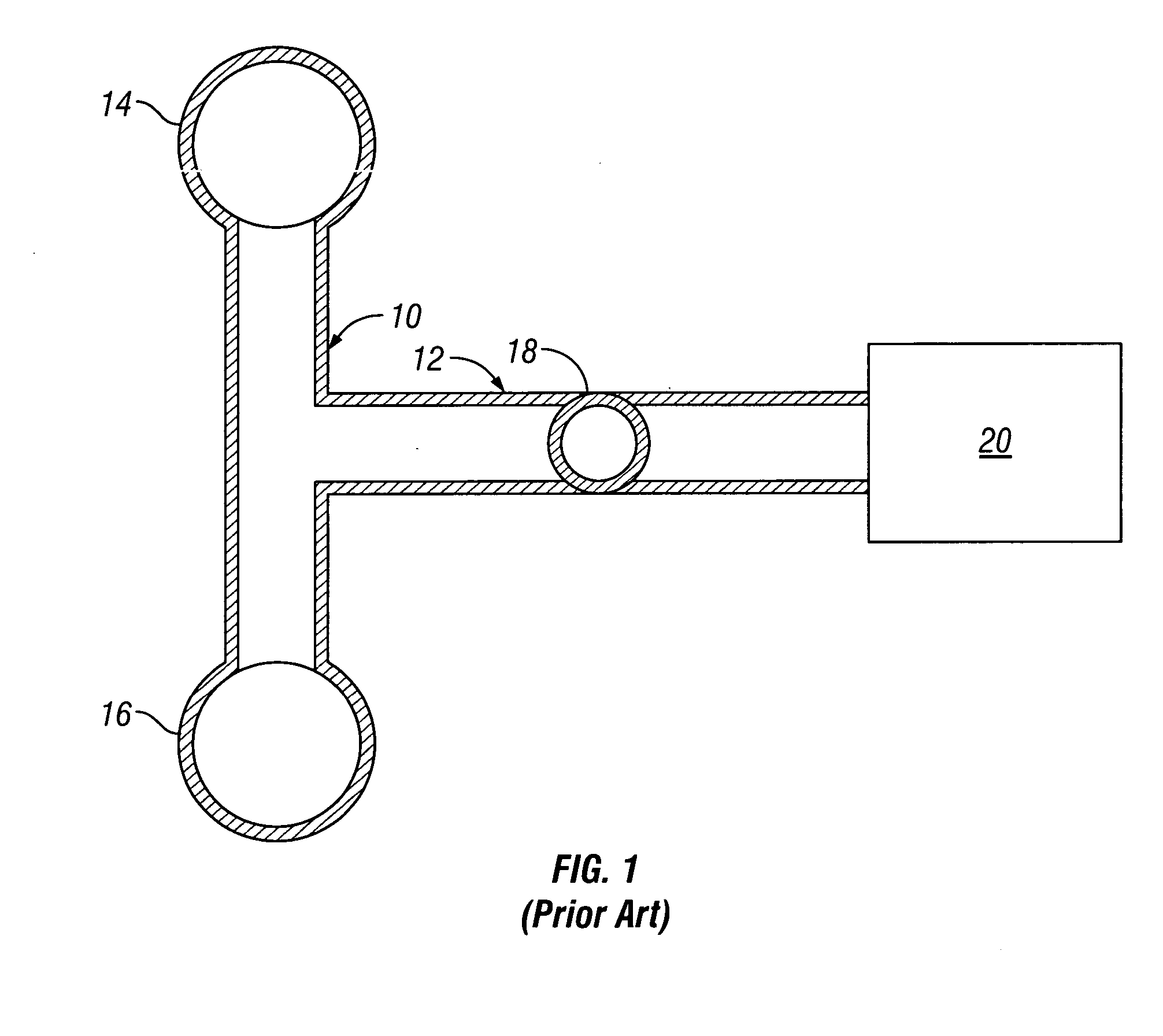
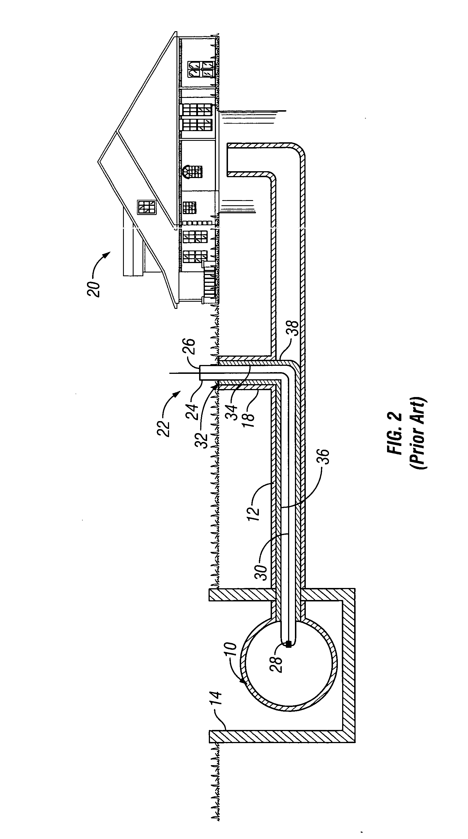
[0038] Referring to the drawings, FIGS. 1 and 2 show a typical prior art construction. A prior art bladder / liner assembly 22 includes a bladder tube 24 having an open end 26 and a closed end 28. A pull line 30 is attached to the closed end 28. A liner tube 32 is positioned on the exterior of the bladder tube after inversion. As can be seen from FIG. 2, the liner tube 32 includes an access portion 34 of the liner tube 32 within the access pipe 18 and includes a lateral portion 36 of the liner tube 32 within the lateral line pipe 12. A blocked portion 38 of liner tube 32 is between the access portion 34 and the lateral portion 36 and blocks the sewage coming from house 20. Therefore it is necessary to cut out and remove the blocked portion 38 so that sewage can pass from the house 20 to the main line 10. If the cut out does not create a smooth transition between the liner and the host pipe at the invert of the host pipe, then sewage will tend to build up at portion 38 due to a jagged ...


PUM

PropertyMeasurementUnit
Lengthaaaaaaaaaa
Adhesivityaaaaaaaaaa
Areaaaaaaaaaaa

Abstract

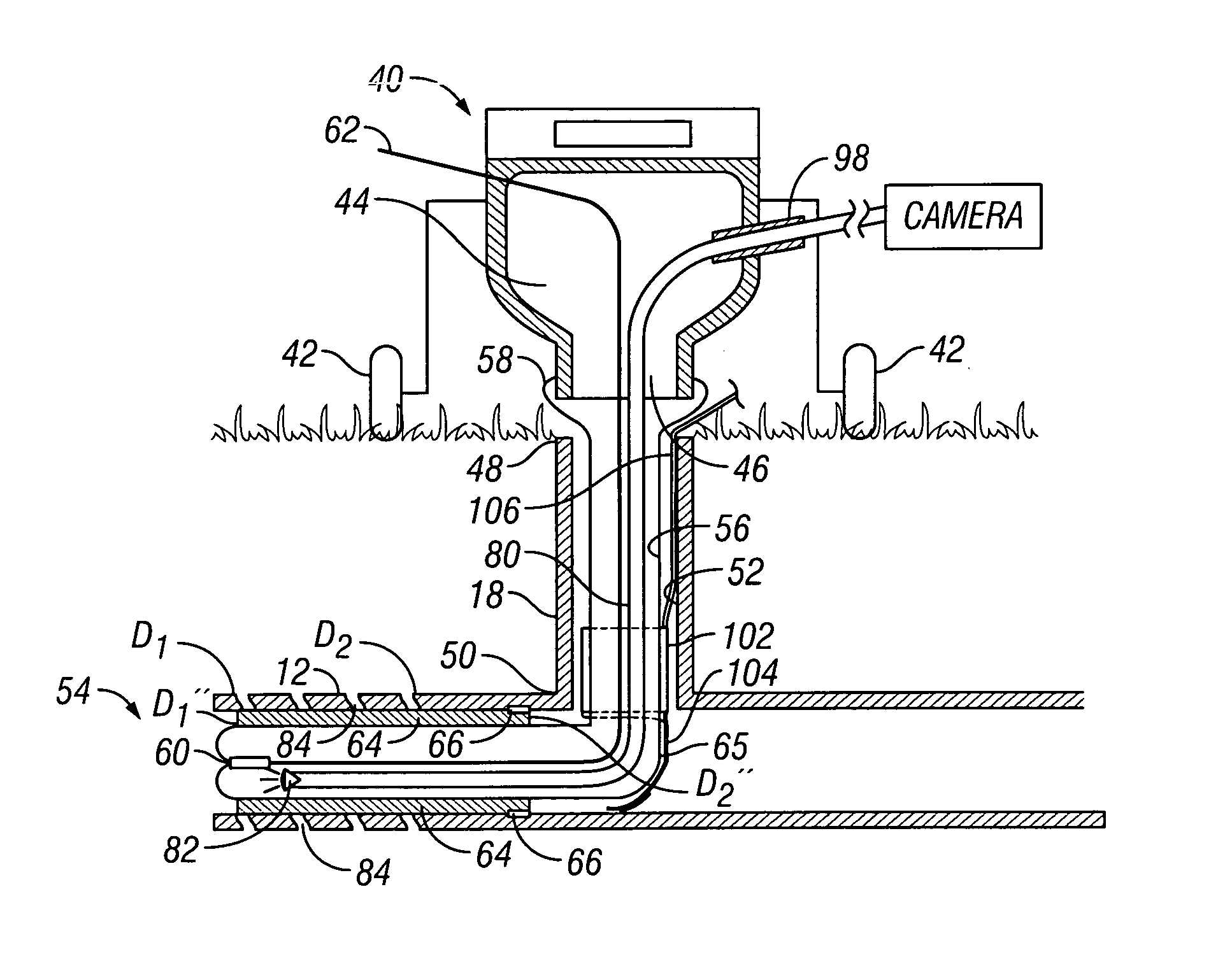
A method of inserting a cured in-place pipe from a cleanout includes positioning a lining along a portion of a length of a bladder, wherein the lining is frangibly connected to the bladder, inserting the bladder through the cleanout, to a position wherein the lining is within the pipe and does not block the pipe.

Description

CROSS-REFERENCE TO RELATED APPLICATIONS [0001] The present application is based upon and claims priority to application Ser. No. 60 / 655,162 filed Feb. 22, 2005.BACKGROUND OF THE INVENTION [0002] The present invention relates to locating a liner within a sewer pipe during pipeline repair and particularly during cured in-place pipeline repair (CIPP). CIPP is typically a fabric tube, impregnated with a liquid resin, formed inside of an existing conduit and cured to become a one-piece, continuous new pipelining. CIPP is used to renew main sewer pipes or lateral sewer pipes as well as other types of conduits. When using CIPP for renewing both main and lateral pipes, the lining is either pulled in place and inflated or inverted and inflated. [0003] A cleanout pipe is typical in all plumbing codes and therefore a cleanout pipe is common on lateral sewer pipes. The cleanout pipe provides one access point for entering the lateral. Another way of access is done remotely through a manhole into...

Claims


Application Information

Patent Timeline
IPC IPC(8): F16L55/16
CPCF16L55/1651
Inventor KIEST, LARRY W. JR.
Owner LMK TECH LLC
Learn More