Al technical title is built by PatSnap Al team. It summarizes the technical point description of the patent document.
a wing and rotor technology, applied in the direction of foil-based vessel movement reduction, underwater equipment, underwater vessels, etc., can solve the problems of unoptimized product and system design, overall drag, etc., and achieve the effect of less thrust, rapid descent, and greater thrus
Active Publication Date: 2006-08-24
FLEXSYS
View PDF34 Cites 42 Cited by
Summary
Abstract
Description
Claims
Application Information
AI Technical Summary
This helps you quickly interpret patents by identifying the three key elements:
Problems solved by technology
Method used
Benefits of technology
[0039] In embodiments of the invention that are used, for example, in connection with submarine propellers, the propeller blades can assume different contours during respective portions of the cycle of rotation. Thus, for example, if it is desired to turn the submarine toward starboard, the starboard half of the cycle of rotation is configured to provide less thrust than the port half of the cycle of rotation. Similarly
Problems solved by technology
Absent the ability to vary the surface contour in any such application results in the creation of products and systems that are not optimally designed, but instead are configured as compromises between conflicting design goal
Method used
Image
Click on the blue label to locate the original text in one second.
Reading with bidirectional positioning of images and text.
Examples
Embodiment Construction
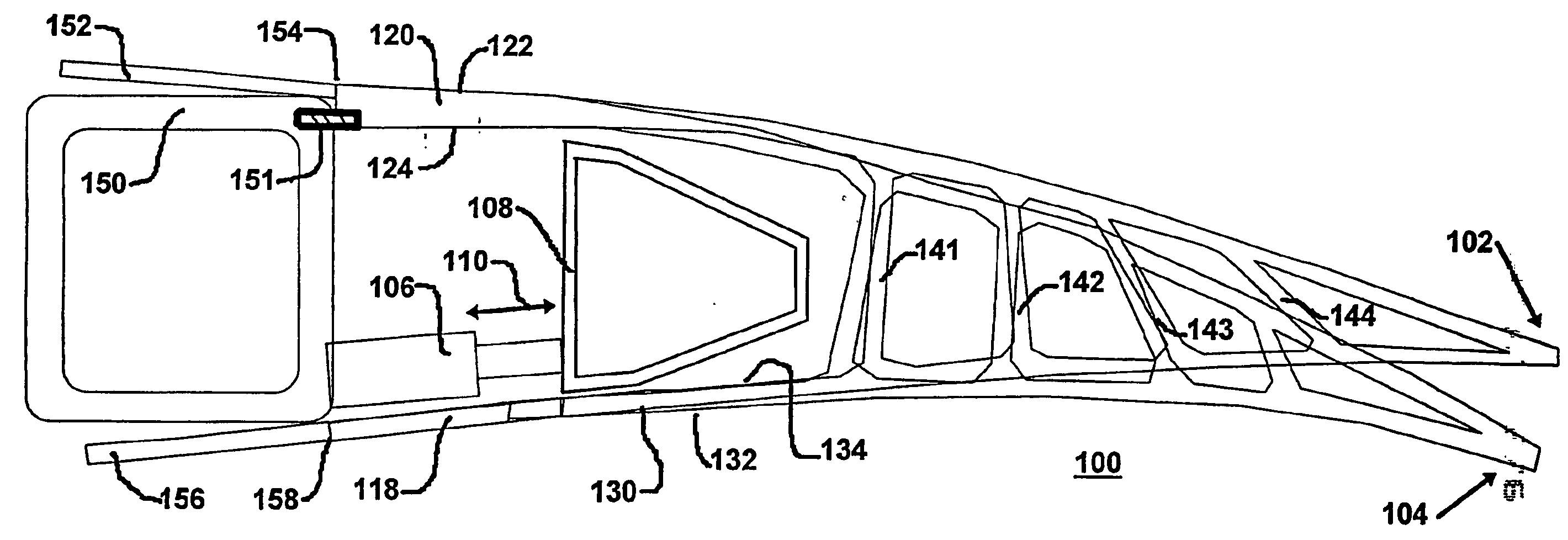
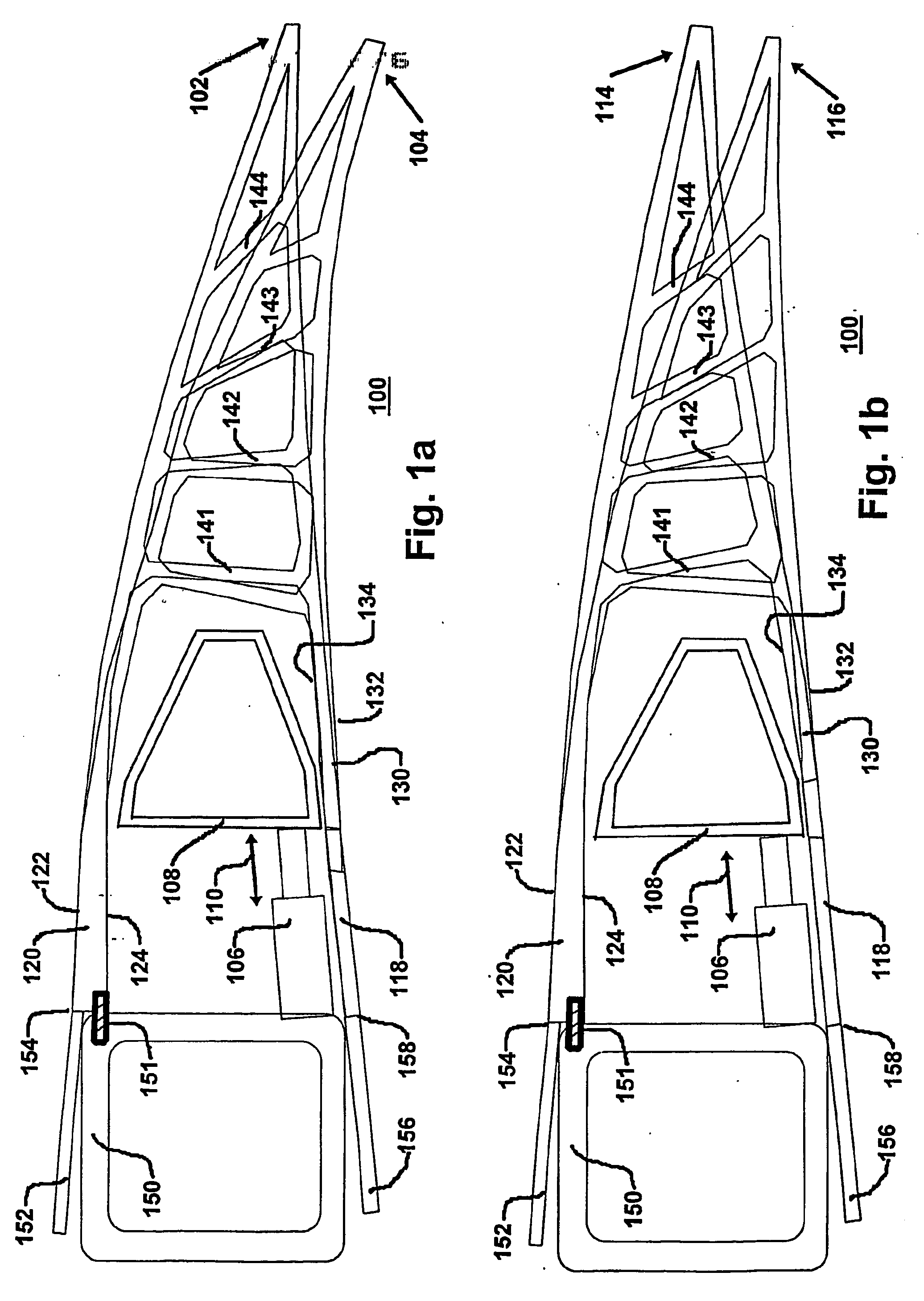
[0070]FIG. 1a is a simplified schematic representation of a compliant structure 100 having a shape characteristic that is varied in response to a moving fluid, such as air or water (not shown). in the figure, the compliant structure being shown in a positive flap deflection condition at position 102 and in downwardly deformed condition at position 104. The positions are determined by operation of an actuator 106 that applies a linear force, in this specific illustrative embodiment of the invention, to a drive tube 108 in the direction of arrow 110. Drive tube 108 is shown cross-sectionally and arranged to extend in a direction substantially perpendicular to the plane of the figure.
[0071]FIG. 1b is a simplified schematic representation of compliant structure 100 of FIG. 1a, the compliant structure being shown in a negative flap deflection condition at position 114 and in a nominal condition at position 116. Elements of structure that bear analogous correspondence to those discussed ...
PUM
Abstract
Variation in the contours of first and second compliant surfaces is produced by a compliant frame having a first resiliently variable frame element (120) having a corresponding first outer surface (122) and a first inner surface (124), and a second resiliently variable frame element (130) having a corresponding second outer surface (132) and a second inner surface (134). The first and second outer surfaces (122, 132) communicate with respective ones of the first and second compliant surfaces. A linkage element (141-144) having a predetermined resilience characteristic is coupled at a first end thereof to the first inner surface (124) and at a second end thereof to the second inner surface (134). A frame coupler (151) couples the first resiliently variable frame element (120) to a support element (150). An actuator (106) applies a force to the second resiliently variable frame element (130) with respect to the support element (150), resulting in a corresponding variation in the contour of the first and second compliant surfaces.
Description
RELATIONSHIP TO OTHER APPLICATION [0001] This application claims the benefit of U.S. Provisional Patent Application Ser. No. 60 / 451,812 filed Mar. 3, 2003, which is a continuation-in-part of U.S. Ser. No. 10 / 316,661 filed Dec. 10, 2002, which is a continuation of U.S. Ser. No. 09 / 600,822 filed Sep. 21, 2000, now U.S. Pat. No. 6,491,262 issued Dec. 10, 2002; U.S. Ser. No. 09 / 600,822 being a §371 or United States National Stage of PCT / US99 / 00901 filed on Jan. 15, 1999 which also claims the benefit of U.S. Ser. No. 09 / 007,309 filed Jan. 15, 1998, which issued as U.S. Pat. No. 5,971,328 on Oct. 26, 1999, the disclosures of all of which are incorporated herein by reference.GOVERNMENT RIGHTS [0002] This invention was made in part under contract, awarded under SBIR Contract No. F33615-01-C-3100 Air Force Research Lab, Air Vehicles Directorate. The government has certain rights in the invention.BACKGROUND OF THE INVENTION [0003] 1. Field of the Invention [0004] This invention relates genera...
Claims
Application Information
Patent Timeline
Application Date:The date an application was filed.
Publication Date:The date a patent or application was officially published.
First Publication Date:The earliest publication date of a patent with the same application number.
Issue Date:Publication date of the patent grant document.
PCT Entry Date:The Entry date of PCT National Phase.
Estimated Expiry Date:The statutory expiry date of a patent right according to the Patent Law, and it is the longest term of protection that the patent right can achieve without the termination of the patent right due to other reasons(Term extension factor has been taken into account ).
Invalid Date:Actual expiry date is based on effective date or publication date of legal transaction data of invalid patent.