Auto-gyro rotor flying electric generator (FEG) with wing lift augmentation

a technology of electric generators and rotors, applied in the direction of electric generator control, renewable energy generation, greenhouse gas reduction, etc., can solve the problems of little or no excess torque available for generating power, and achieve the effect of full generating capacity, reduced wind speed, and increased rotor angle of attack

Inactive Publication Date: 2016-01-14
SKY WINDPOWER CORP
View PDF3 Cites 30 Cited by
  • Summary
  • Abstract
  • Description
  • Claims
  • Application Information

AI Technical Summary

Benefits of technology

[0011]This invention is directed to auto-gyro rotor FEGs that include airfoil wings as well as auto-gyro rotors to provide lift to the vehicles. The addition of wings to the FEGs allows them to reach full generating capacity in lower wind speeds. The addition of the wings also allows the vehicles to operate at higher rotor angles of attack, which exposes more of the rotor blade area to the wind. Power generation increases with greater rotor angle of attack.
[0012]The FEGs of the present invention include both forward and rear wings which are preferable pairs of wings that are either fixedly or pivotally mounted on opposite sides of a fuselage. In the preferred embodiments shown herein, the front wings are of a conard type and are smaller than the rear wings. The front wings are mounted along a forward portion of the fuselage and the rear wings are mounted along a rear portion of the fuselage. The rear wings will also be provided with ailerons to facilitate maneuvering of the FEGs about a roll axis about a center axis of the fuselage and the wings may also be swept to a rear of the FEGs.
[0013]With the addition of airfoil wings to the FEGs there is an increase in lift to the FEGs, allowing less of the thrust created by the rotors to be used to retain the vehicles aloft. When the rotors are required to create less of a vertical component of thrust, they can have their blade collective pitch reduced, which increases torque available for generating electrical power. Alternatively, reducing the requirement of creating lift to retain the FEGs aloft by the rotors allows an increase in the rotor plane angle of attack, as the thrust vector can be made more horizontal if less of the vertical component of power is required. Increasing the vehicles angle of attack increases thrust and torque available for generating power. Also, a combination of both decreasing blade pitch and increasing rotor plane angle of attack may also be used, both contributing to increasing quantity of power being generated. In these ways, the addition of wings can increase the power generated by the FEGs at given wind speeds.
[0014]The addition of airfoil wings to the FEGs can also increase the availability of FEGs. Availability is a measure of the fraction of time wind turbines may produce rated power from the wind. Wind speed is often below the minimum required for the FEGs to achieve maximum power generation. This is because at low wind speeds, a majority of the thrust created by the rotors is used to create sufficient lift to keep the FEGs and their tethers aloft. This leaves little or no excess torque available for generating power. Airfoil wings designed to operate at low wind speeds can provide most of the necessary lift to keep the FEGs aloft, allowing the vertical component of thrust from the rotors to be reduced, which allows the FEGs to generate more power as explained above.
[0017]In the first embodiment, as each rotor receives undisturbed direct wind energy at all phases of flight, there are no discontinuities in control based on angle of attack and wind speed. This allows for a smooth transition from takeoff and hovering flight to kite-like power generating flight.
[0018]In accordance with the invention, the intermediate portion of the elongated fuselage is raised outwardly and above the upper surfaces of the fore and aft portions of the fuselage so that the central hub of the rotor assembly is mounted at a center of gravity of the FEG. In the first variation of the first embodiment, the rotor assembly is pivotally mounted about a pivot axis which is perpendicular with, but coplanar to, a central elongated axis defined by the fore and aft portions of the fuselage. This allows a relative change in pitch between the rotors and the fuselage during flight. The central fuselage houses the avionics and computer systems necessary for FEG control, the electronics necessary to communicate with the ground, motor control electronics, and electrical power conversion electronics.

Problems solved by technology

This leaves little or no excess torque available for generating power.

Method used


Image

  • Auto-gyro rotor flying electric generator (FEG) with wing lift augmentation
  • Auto-gyro rotor flying electric generator (FEG) with wing lift augmentation
  • Auto-gyro rotor flying electric generator (FEG) with wing lift augmentation

Examples


Embodiment Construction

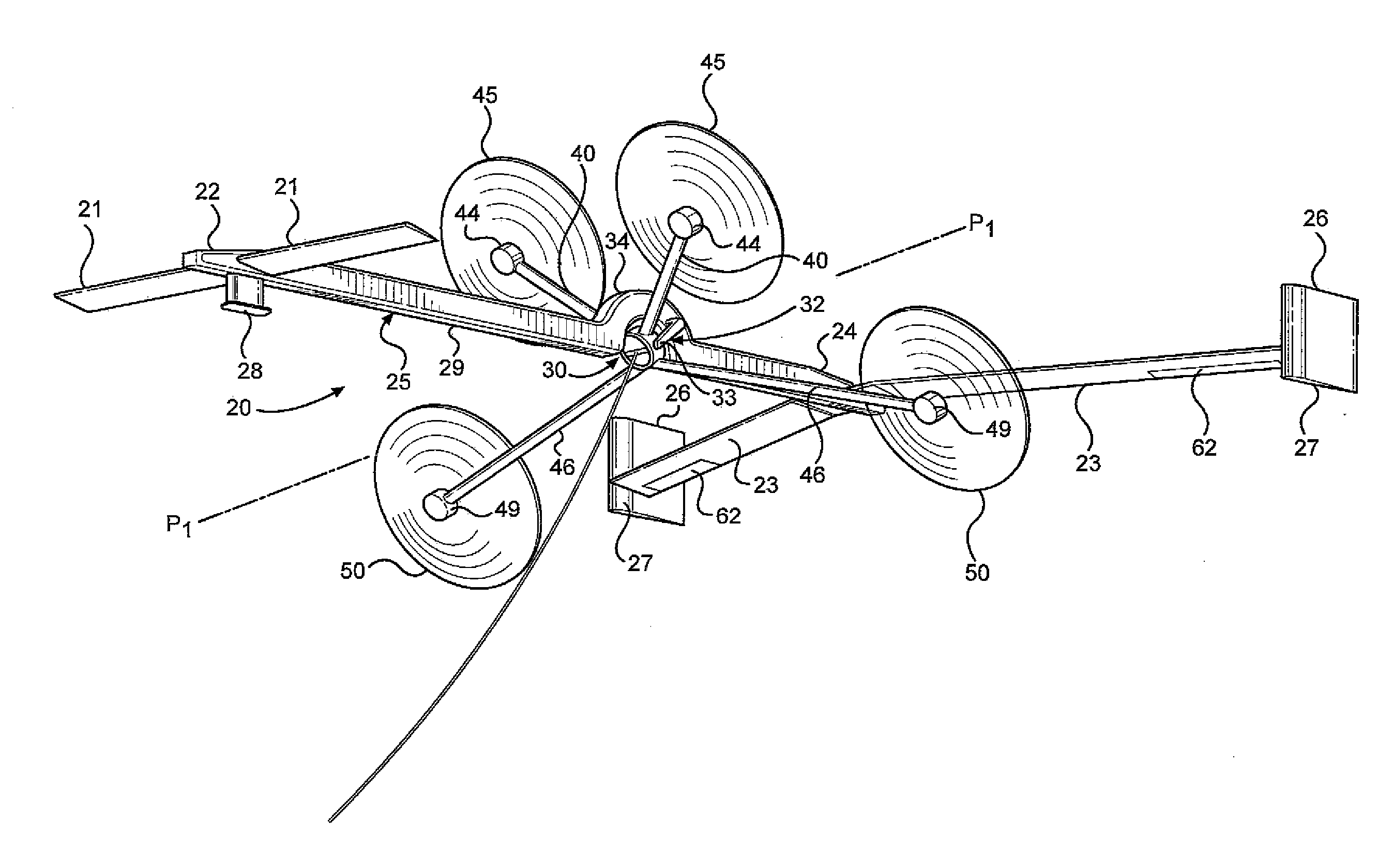
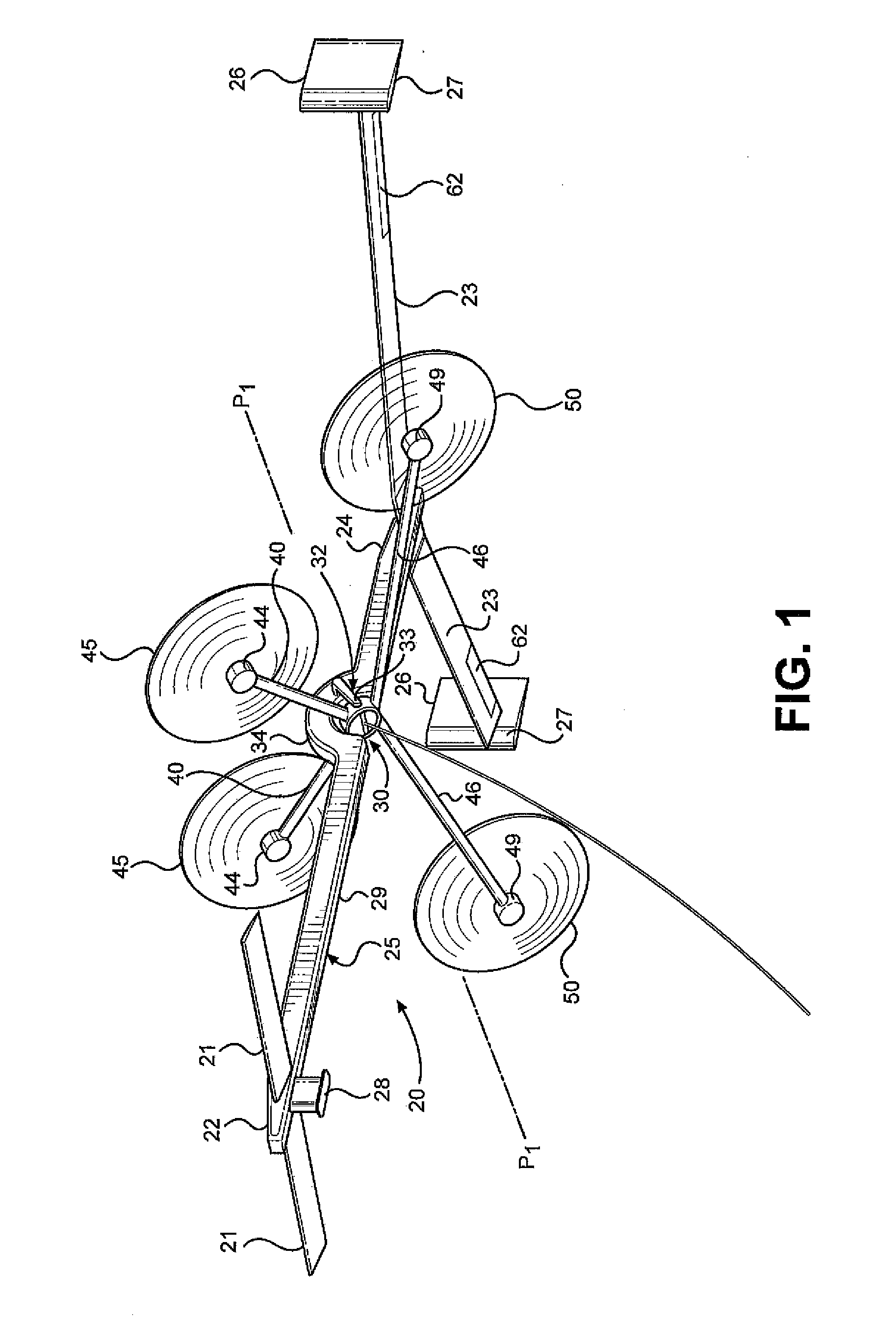
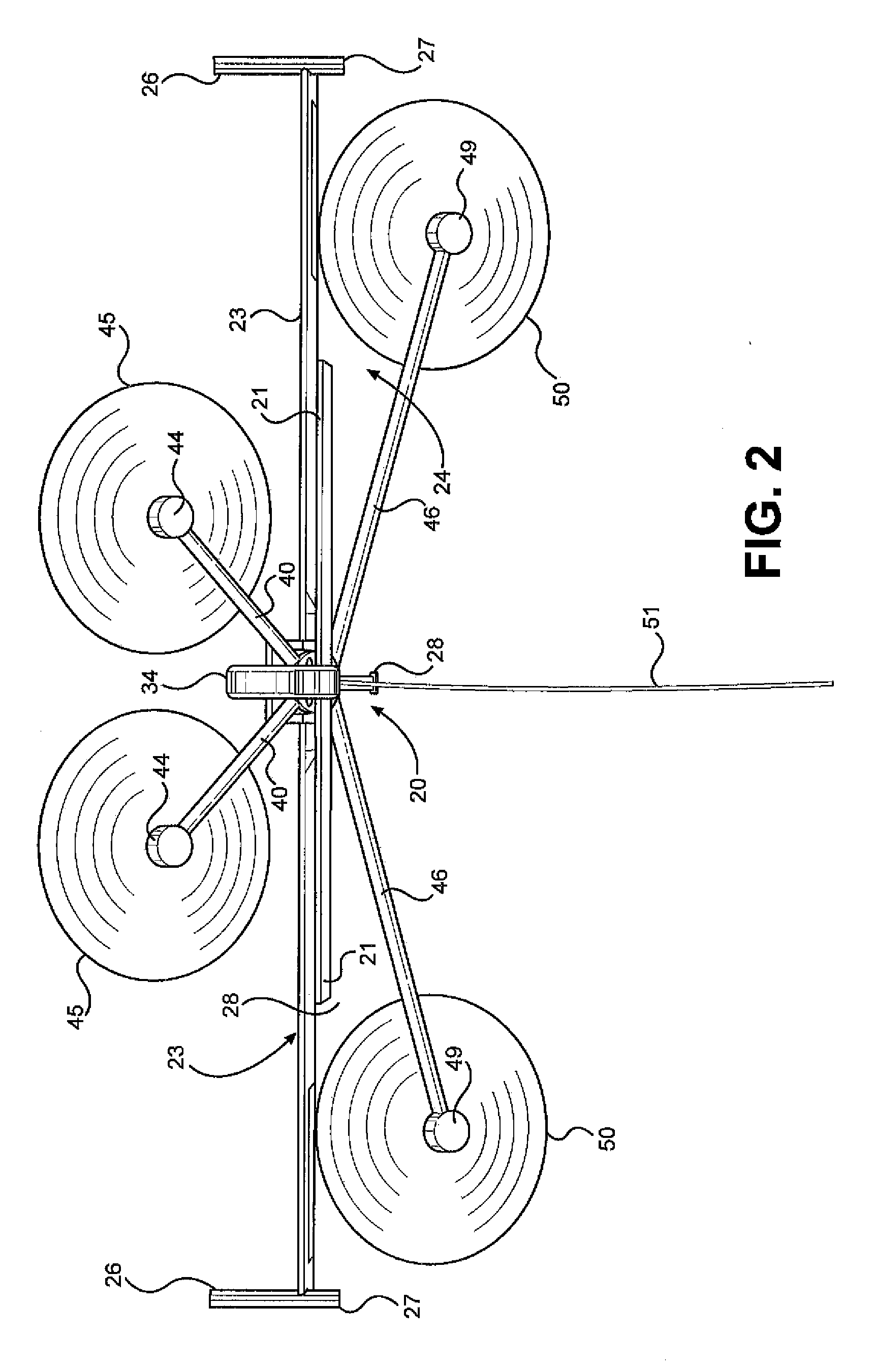
[0042]The invention combines an auto-gyro rotor FEG 20 with airfoil wings to provide some of the lift necessary to keep the vehicle aloft while generating electrical power. The auto-gyro rotor FEG can have any even number of rotors preferably equal to or greater than four and can have a symmetric rotor layout, as shown in FIGS. 13 and 14, or a staggered rotor configuration, as shown in FIG. 15. The staggered rotor layout, which is a first preferred embodiment of the invention, allows downwind rotors to receive clean air which is air that is not disturbed by upwind rotors during the transition from a zero angle of attack of the rotor plane, which is necessary for vertical takeoff, to a high rotor plane angle of attack used for power generation.

[0043]The invention vehicles or FEGs described in detail herein have four auto-gyro rotors, and both types of rotor layouts are described. More rotors can be added by adding pairs of rotors symmetrically to each side of the vehicle. The inventi...


PUM


Abstract

A flying electric generator for obtaining power from wind currents which includes a fuselage having fore and aft portions and an intermediate portion, a rotor assembly including at least two forward rotors mounted on a pair of forward extending support arms extending from the fuselage and at least two rear rotors mounted to a pair of rearward extending support arms extending from the fuselage and at least one first forward wing mounted to a forward portion of the fuselage and extending outwardly on opposite sides of the fuselage and at least one second rear wing mounted to a rear portion of the fuselage and extending outwardly on opposite side of the fuselage.

Description

BACKGROUND OF THE INVENTION[0001]1. Field of the Invention[0002]The present invention relates to the field of flying electric generators (FEG) and more particularly to a new configuration of auto-gyro rotor flying electric generators featuring wing lift augmentation.[0003]2. Brief Description of the Related Art[0004]The idea of flying electric generators is not new, and several methods of extracting energy from the high altitude winds have been proposed and are now in development. It is well known that the energy content in wind increases with distance from the ground (altitude). Current wind turbine technologies attempt to take advantage of this fact by reaching ever higher, but their cantilever design limits their maximum height, as large and costly steel and concrete bases are required to react against the bending forces introduced by their necessary structural geometry. Flying electric generators or FEGs in contrast require only a thin, light tether attached to a small ground an...

Claims


Application Information

Patent Timeline
Patent Type & Authority Applications(United States)
IPC IPC(8): F03D9/00B64C27/08F03D1/02
CPCF03D9/002F03D1/02B64C2201/12B64C27/08F03D11/04F03D3/02Y02E10/74F03D5/00F05B2240/40F05B2240/921Y02E10/70F03D13/20F03D9/25Y02E10/728F03D9/30Y02E10/72B64U2101/00
Inventor AUSTIN, ROBERT
Owner SKY WINDPOWER CORP
Why Eureka
Try Eureka