Electric powered flying wing toy

a technology of electric motors and flying wings, which is applied in the direction of toy aircraft, remote control toys, transportation and packaging, etc., can solve the problems of inconvenient positioning, inconvenient use, and inability to use landing gear, so as to improve the gliding efficiency of the flying wing body, reduce the audible noise, and prevent the propulsion system from overheating

Inactive Publication Date: 2008-05-27
CHAMBERLAIN MARK SPENCER
View PDF12 Cites 15 Cited by
  • Summary
  • Abstract
  • Description
  • Claims
  • Application Information

AI Technical Summary

Benefits of technology

[0013]The disclosed embodiments of the present invention are directed to a radio controlled, electric motor propelled flying wing toy incorporating novel features described herein. A pusher propeller thrust system consisting of an electric motor and propeller is inside a streamlined motor enclosure installed to extend beyond the trailing wing edge. The enclosure extends partially or fully into the wing and extends beyond the trailing edge of the aircraft wing. Extending the propeller away from the trailing edge improves propeller thrust efficiency because the propeller encounters less turbulent air and less interference between the propeller-induced turbulence and the trailing edge of the wing. For an aircraft that is flying normally (i.e., non-inverted), airflow tends to delaminate (break up into turbulent airflow) on the top wing surface first, in part because the air pressure is lower on the top wing surface than it is on the bottom wing surface. The flying wing body, as described in this invention, is designed with smooth airfoil contours forward of the streamlined motor enclosure, motor and propeller system, offering superior laminar air flow behavior over a greater portion of the wing, particularly over the top wing surface, upstream of the propeller. The combination of innovations described above results in increased propeller thrust efficiency and reduced audible propeller noise. Increased propeller thrust efficiency is an important benefit because electric propulsion systems in general offer less thrust per unit mass when compared to internal combustion type engines commonly used in the radio control hobby market.
[0014]The present invention offers a means of securing the battery pack completely within the wing, accessible from the bottom surface, capable of retaining the battery during high speed aerobatic maneuvers, while retaining a smooth airfoil contour underneath, through the combined implementation of a resilient battery bay pouch, and a flexible cover flap that locks the battery in place and covers the battery bay opening and pouch.
[0015]The present invention offers a means of securing the battery in such a fashion that it is not ejected from the craft upon impact, the foam wing structure itself absorbs the kinetic energy of the battery mass upon impact, the battery can be quickly and easily installed and removed, and the combined battery and propulsion system are sufficiently air-cooled during flight.

Problems solved by technology

Typically no landing gear is used because these toy craft are hand launchable and can land gently in the grass or can be hand caught.
Frequently, such hilly terrain is unavailable or inconveniently located, or the weather conditions are not conducive to slope soaring.
This causes propeller thrust inefficiencies because the wing, and in particular, the trailing edge of the wing generates turbulence that interferes with smooth propeller air flow.
This configuration also increases the audible noise level generated by the propeller system.
Because the airfoil thickness of original flying wing glider designs does not fully accommodate the larger battery inside the wing, the battery is typically placed on top of, underneath, or is partially embedded into the wing.
The disadvantages of this design include substantial interference from the fuselage with airflow to the rearwardly-located pusher propeller.
Upon hard nose impact with the earth or a stationary object, the thermoplastic cracks or shatters and the battery, also secured to the plane using Velcro fasteners, can eject from the craft, posing a human safety hazard and potentially damaging the battery and all electronics connected to the battery.

Method used


Image

  • Electric powered flying wing toy
  • Electric powered flying wing toy
  • Electric powered flying wing toy

Examples


Embodiment Construction

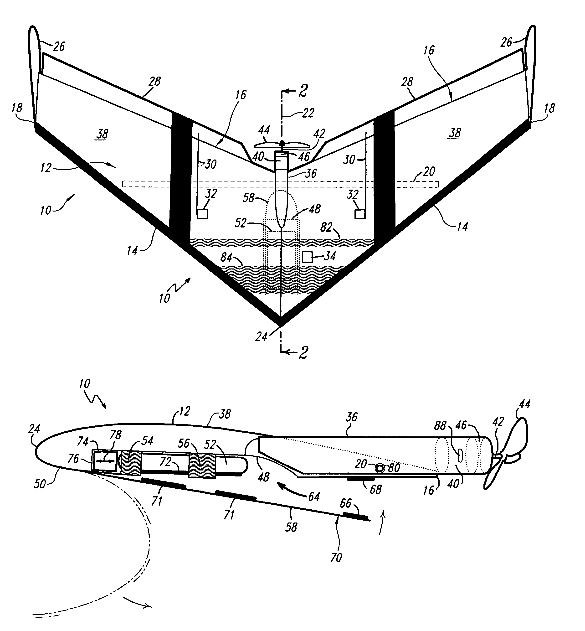
[0026]Generally, the present invention utilizes a form-fitting motor enclosure, allowing the motor and propeller to extend rearward, while minimizing interference of air flow between the aircraft nose and pusher propeller. The motor enclosure extension combines with the extension of the propeller shaft to position the propeller away from the wing trailing edges.

[0027]The net propeller extension improves propeller thrust efficiency and reduces audible propeller noise. Improved thrust efficiency increases aircraft climb rate at full throttle, and allows the operator to continuously cruise the flying wing at lesser throttle, thereby extending flight time before the battery becomes discharged.

[0028]Particularly for an aircraft that is cruising normally (i.e., non-inverted), airflow tends to delaminate (break up into turbulent airflow) on the top wing surface first, in part because the air pressure is lower on the top wing surface than it is on the bottom wing surface. The flying wing bo...


PUM


Abstract

A radio-controlled electrically-powered model flying wing aircraft having a pusher propeller at the rear wing root powered by an electric motor mounted in a streamlined electric motor housing that extends into the wing and blends smoothly into the wing surface at the center wing chord. The motor housing, motor and propeller extend beyond the wing trailing edges to ensure efficient propeller operation and to reduce propeller-induced noise. A battery is secured in a resilient pouch and protected completely inside the wing root, serviceable from the bottom wing surface by removing a quick release flap. Major structural elements are composed of impact resistant, flexible, and resilient materials.

Description

BACKGROUND OF THE INVENTION[0001]1. Field of the Invention[0002]This invention relates to a toy model radio controlled, electric motor propelled flying wing.[0003]2. Description of the Related Art[0004]The flying wing is an aerodynamically efficient aircraft, in part because the entire body provides lift, while the fuselage section of a conventional aircraft introduces parasitic drag and offers little to no lift. Northrup describes basic flying wing theory in U.S. Pat. No. 2,406,506.[0005]Commercially-available radio controlled, electric-motor-propelled toy flying wings have been derived from unpowered flying wings (gliders), typically used for soaring over slopes. The wings of such gliders are typically constructed using resilient EPP (expanded polypropylene) foam, offering light weight and impact resistance. To increase airframe stiffness, one or more spar shafts are embedded inside the EPP wings. The physical arrangement of the spar shaft(s) depends upon the design but could cons...

Claims


Application Information

Patent Timeline
Patent Type & Authority Patents(United States)
IPC IPC(8): A63H27/24A63H27/18A63H30/04B64C13/20B64C39/02B64D27/24
CPCA63H27/02A63H30/04
Inventor CHAMBERLAIN, MARK SPENCER
Owner CHAMBERLAIN MARK SPENCER
Why Eureka
Try Eureka