Method for stabilizing a motor vehicle whose speed is reduced to a rest position and brake system for carrying out said method

US20060186732A1Active Publication Date: 2006-08-24LUCAS AUTOMOTIVE GMBH
6 Cites 4 Cited by

Patent Information

Authority / Receiving Office
US · United States
Current Assignee / Owner
Publication Date
2006-08-24

Smart Images

  • Figure 1
    Figure 1
  • Figure 2
    Figure 2
  • Figure 3
    Figure 3
Patent Text Reader

Abstract

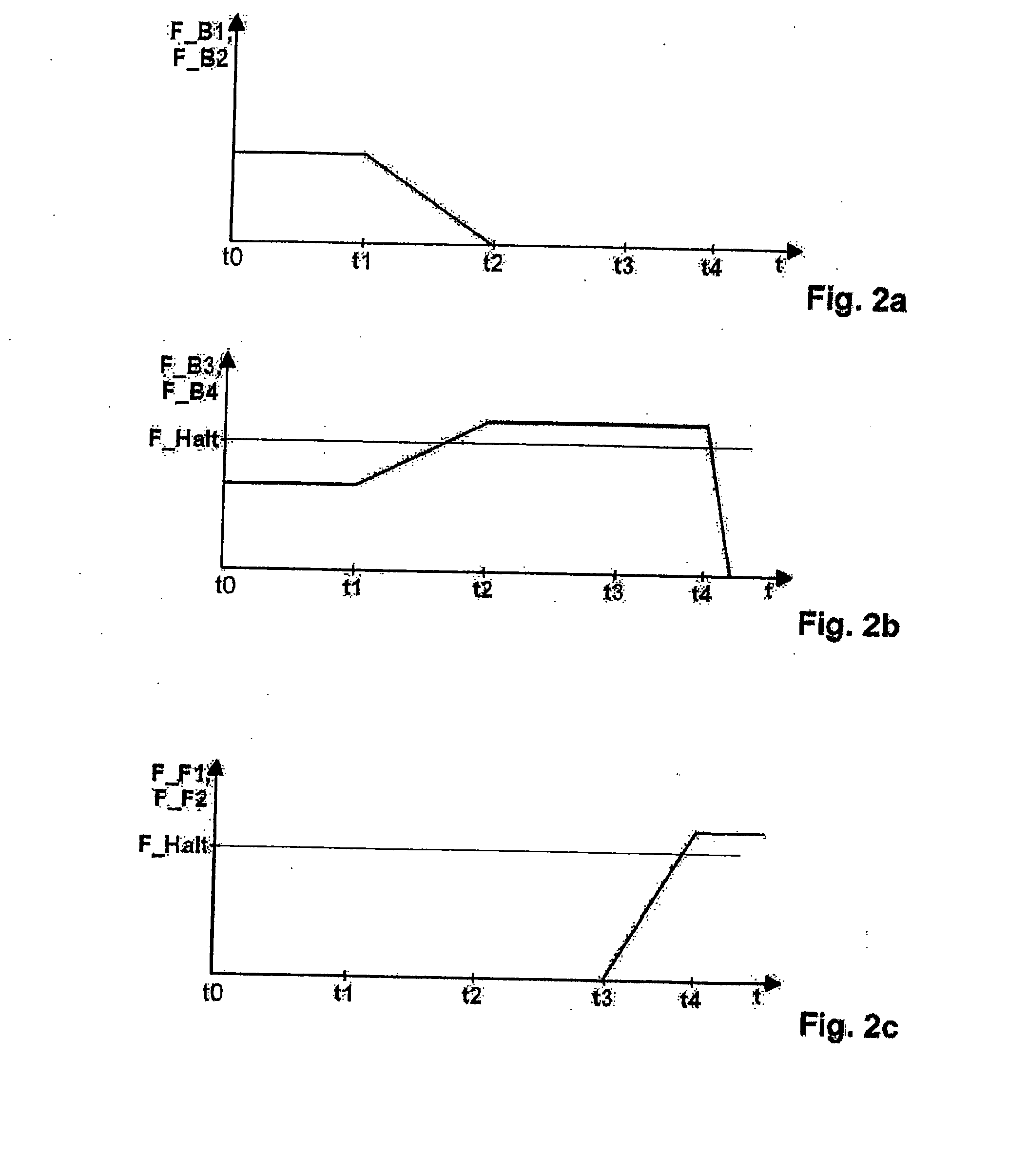
In a method for stabilising a motor vehicle which is decelerated into a rest position and in a corresponding motor vehicle brake system which is provided with a service brake and a parking brake which can be actuated independently of the driver, when activation of the parking brake is initiated, the service brake changes from a first braking-force distribution of a service brake mode to a mode simulating a second braking-force distribution of the parking brake, and a switch-back to the first braking-force distribution of the service brake mode is enabled at least during the transition.
Need to check novelty before this filing date? Find Prior Art

Description

CROSS-REFERENCE TO RELATED APPLICATIONS

[0001] This application is a continuation of International Application No. PCT / EP2004 / 012153 filed Oct. 27, 2004, the disclosures of which are incorporated herein by reference, and which claimed priority to German Patent Application No. 103 51 025.7 filed Oct. 31, 2003, the disclosures of which are incorporated herein by reference.BACKGROUND OF THE INVENTION

[0002] The present invention relates to a method for stabilising a motor vehicle which is decelerated into a rest position and is provided with a service brake and a parking brake which can be actuated independently of the driver, and to a corresponding motor vehicle brake system.

[0003] It is already known to provide motor vehicle brake systems with a service brake and a parking brake which can be actuated independently of the driver. For example, EP 0 825 081 B1, and corresponding U.S. Pat. No. 6,019,436 A1, both of which are incorporated by reference herein, describes a brake system of ...

Examples

Embodiment Construction

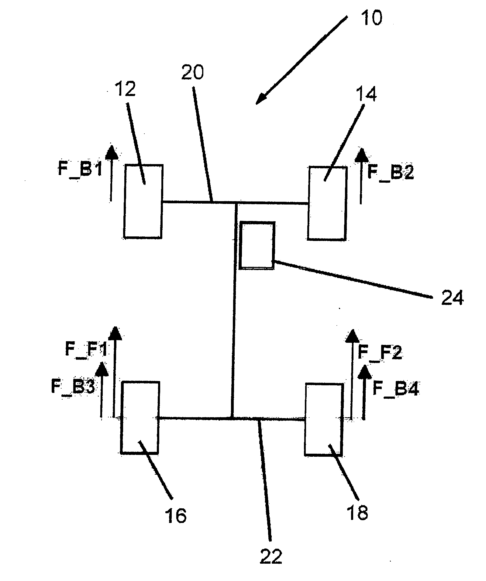
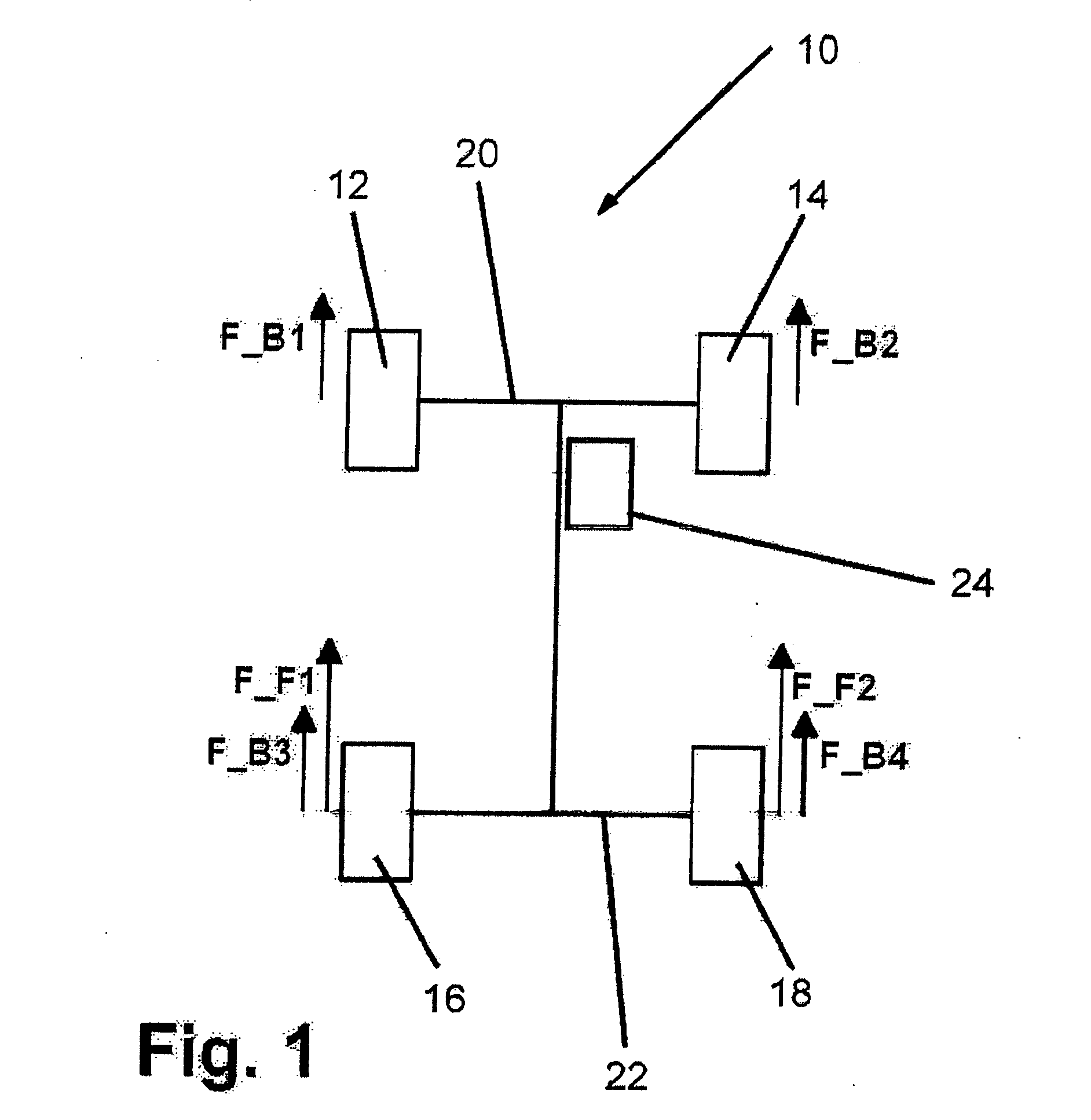
[0018]FIG. 1 shows a schematically represented motor vehicle which is generally designated by 10. This comprises four wheels, namely the two front wheels 12 and 14 and the two rear wheels 16 and 18.

[0019] The two front wheels 12 and 14 are coupled via a front axle 20, while the two rear wheels are coupled via a rear axle 22. A service brake, the control of which is generally designated by 24, acts on all four wheels 12, 14, 16 and 18. In the service brake mode the service braking force F_B1 acts on the front wheel 12, the serving braking force F_B2 on the front wheel 14, the service braking force F_B3 on the rear wheel 16 and the service braking force F_B4 on the rear wheel 18. However in the parking brake mode, for example when the vehicle has been parked, in the example holding forces only act on the two rear wheels 16 and 18, namely the holding force F_F1 on the rear wheel 16 and the holding force F_F2 on the rear wheel 18. These holding forces are applied by the parking brake. ...