Shielding for mobile MR systems

a mobile mri system and shielding technology, applied in the direction of superconducting magnets/coils, magnetic bodies, instruments, etc., can solve the problems of system damage, limited performance of such mobile mri systems, and increase the effect of effects, so as to improve the stability of magnetic fields

Active Publication Date: 2006-08-24
SIEMENS MEDICAL SOLUTIONS USA INC +1
View PDF10 Cites 41 Cited by
  • Summary
  • Abstract
  • Description
  • Claims
  • Application Information

AI Technical Summary

Benefits of technology

[0006] Still another object of the invention is to provide a transportable MRI system and housing, in which the MRI system exhibits improved magnetic field stability in the case of deformation of the housing due to the effects of terrain and the environment.

Problems solved by technology

Measurements of field strength for a known MRI system installed in a mobile trailer indicated that the system suffered from field instabilities, resulting from movement of the shielding steel mounted to the walls of the trailer.
All such effects can be increased due to twisting of the trailer when mounted on uneven ground.
Such effects are known to limit the performance of such mobile MRI systems.

Method used


Image

  • Shielding for mobile MR systems
  • Shielding for mobile MR systems
  • Shielding for mobile MR systems

Examples


Embodiment Construction

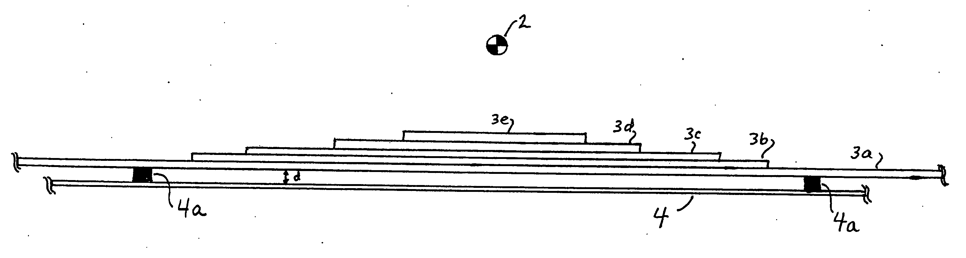
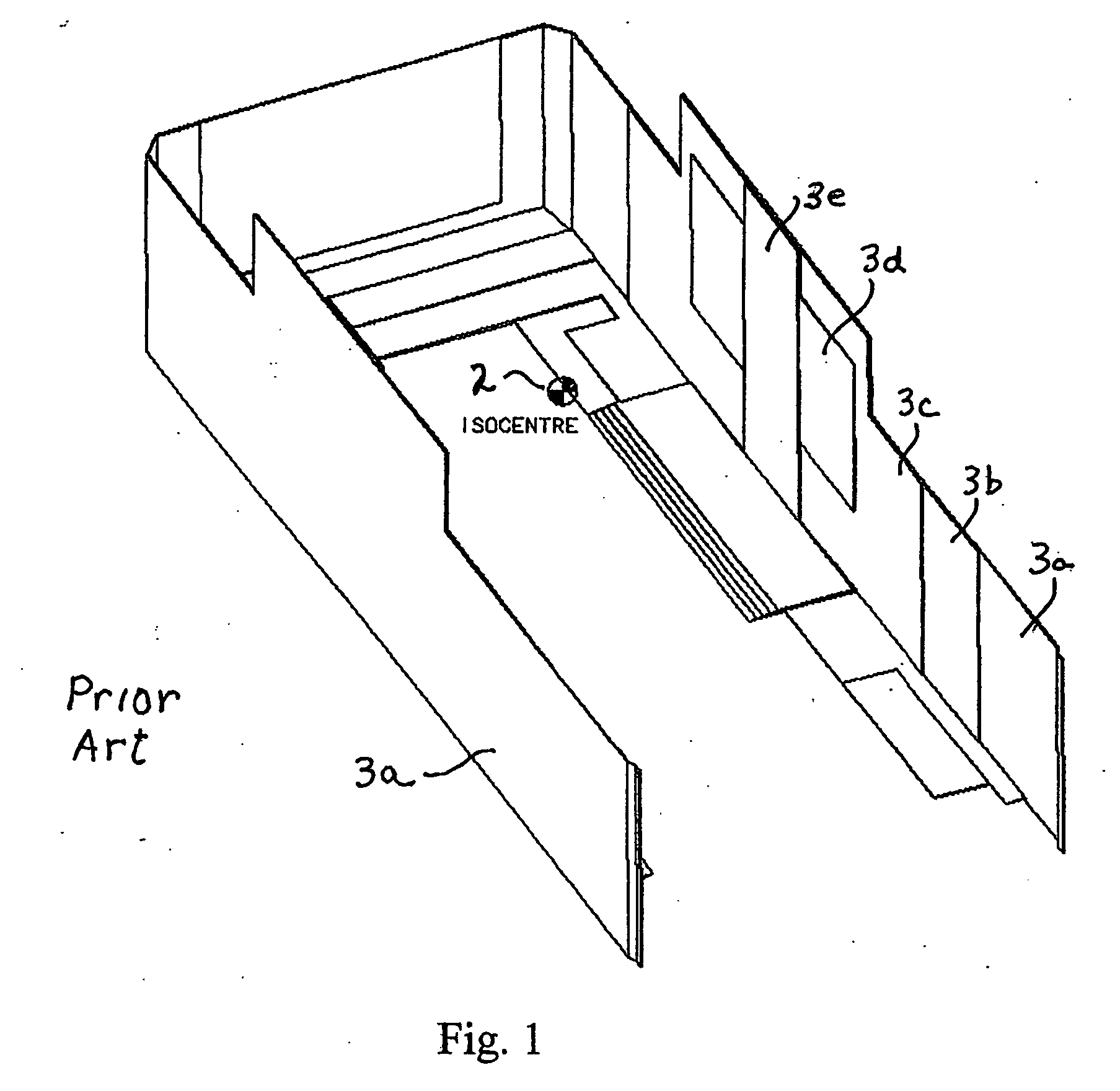
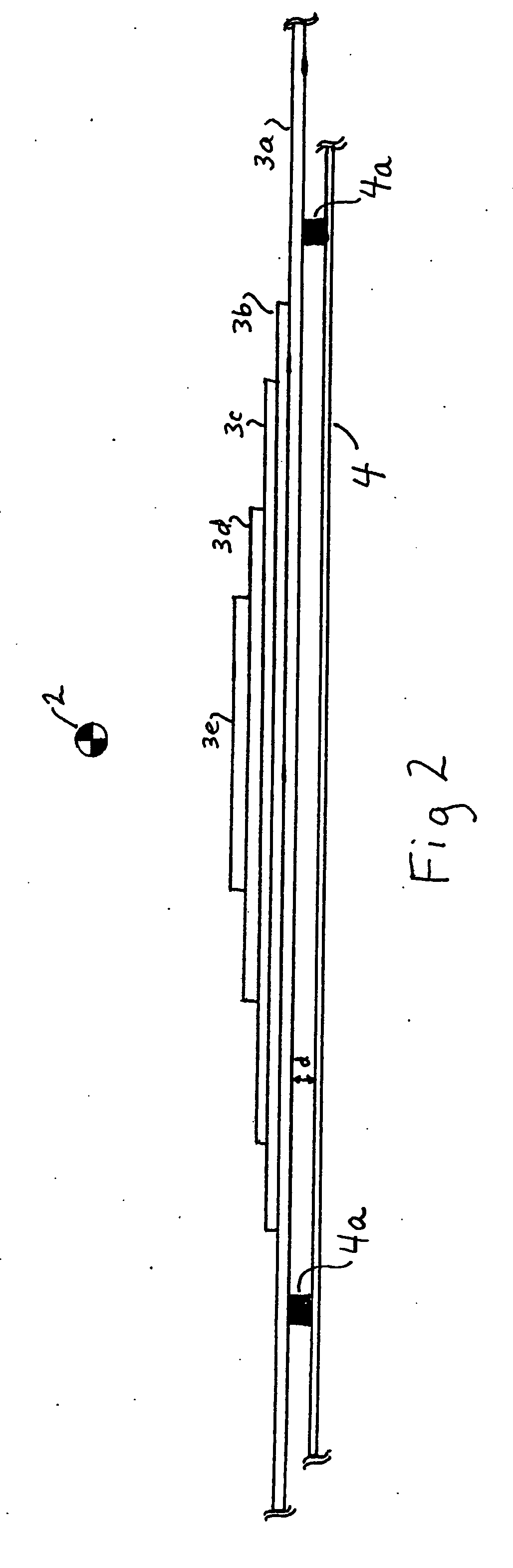
[0015]FIG. 1 is a schematic depiction of a conventional magnetic shielding structure 1 for a trailer (not shown) which houses a mobile MRI system (not shown). (For simplicity, and to facilitate understanding, only a portion of the overall shielding is illustrated, in broken away form.) The isocenter 2 of the strong magnetic field generated by the MRI system is situated in approximately a center portion of the interior volume of the trailer and the shielding. The function of the shielding is to contain the magnetic field within the trailer, and to prevent, to the greatest extent possible, its propagation outside the trailer walls (not shown).

[0016] As can be seen in FIG. 1, the conventional shielding arrangement includes a plurality of shielding layers of a ferromagnetic material, which are “stacked” in the inward direction, in layers of successively smaller lateral size, (with the lateral extent decreasing within the stack toward the midsection of the enclosure). As shown schematic...


PUM

PropertyMeasurementUnit
magnetic fieldaaaaaaaaaa
magnetic shieldingaaaaaaaaaa
thermal insulationaaaaaaaaaa

Abstract

A trailer for housing a mobile MRI system has magnetic shielding in the form of a plurality of sheets of magnetic material which are supported within the trailer, by a rigid supporting structure or frame. The layers are arranged in a stacked or laminar configuration with the laterally longest layer disposed inward of the remaining layers, such that the width of the gap between that layer and the exterior walls of the trailer at the lateral extremities of the shielding is greater than its width in a central area. The rigid frame maintains the gap and prevents contacting of the shielding and the trailer walls.

Description

BACKGROUND OF THE INVENTION [0001] The present invention is directed to a magnetic shielding arrangement for a mobile MRI system which is mounted in a transportable housing, such as a trailer or prefabricated structure. [0002] Magnetic shielding of a trailer for carrying a mobile MRI (magnetic resonance imaging) system must meet the following criteria: it must contain the magnetic field in accordance with applicable regulations for stray field; adherence to the static site shim specifications must be maintained; and the trailer shielding must not compromise the short-term field stability of the MRI system through bulk movement of the shield. [0003] Measurements of field strength for a known MRI system installed in a mobile trailer indicated that the system suffered from field instabilities, resulting from movement of the shielding steel mounted to the walls of the trailer. In particular, temporal effects on the magnetic field have been attributed to movement of the shielding steel c...

Claims


Application Information

Patent Timeline
Patent Type & Authority Applications(United States)
IPC IPC(8): G01V3/00H01F7/00G01R33/28G01R33/421H01F6/00H01F27/36H05K9/00
CPCG01R33/28G01R33/421H01F6/00H01F27/365H05K9/0003
Inventor MALLETT, MICHAEL JOHN DISNEYPIETSCH, MICHAELSENSENEY, MICHAEL ALANSIMMERS, JOSHUA ANDREWTROWELL, STEPHEN PAULTIGWELL, NEIL CHARLESWILLIAMS, JEREMY FRANCISDEMARRAIS, SETH MICHAEL
Owner SIEMENS MEDICAL SOLUTIONS USA INC
Why Eureka
Try Eureka