Three-dimensional antenna fabrication from a two-dimensional structure

a two-dimensional structure and three-dimensional antenna technology, applied in the field of three-dimensional antenna fabrication, can solve the problem of time-consuming and labor-intensive assembling of three-dimensional antenna arrays, and achieve the effect of fast and inexpensive way of fabricating and assembling

Inactive Publication Date: 2006-08-24
INTERDIGITAL TECH CORP
View PDF1 Cites 22 Cited by
  • Summary
  • Abstract
  • Description
  • Claims
  • Application Information

AI Technical Summary

Benefits of technology

[0005] In view of the foregoing background, it is therefore an object of the present invention to provide a relatively fast and inexpensive way to fabricate and assemble a three-dimensional antenna array.

Problems solved by technology

Moreover, it is also time consuming to assemble three-dimensional antenna arrays.

Method used


Image

  • Three-dimensional antenna fabrication from a two-dimensional structure
  • Three-dimensional antenna fabrication from a two-dimensional structure
  • Three-dimensional antenna fabrication from a two-dimensional structure

Examples


Embodiment Construction

[0025] The present invention will now be described more fully hereinafter with reference to the accompanying drawings, in which preferred embodiments of the invention are shown. This invention may, however, be embodied in many different forms and should not be construed as limited to the embodiments set forth herein. Rather, these embodiments are provided so that this disclosure will be thorough and complete, and will fully convey the scope of the invention to those skilled in the art. Like numbers refer to like elements throughout, and prime notation is used to indicate similar elements in alternative embodiments.

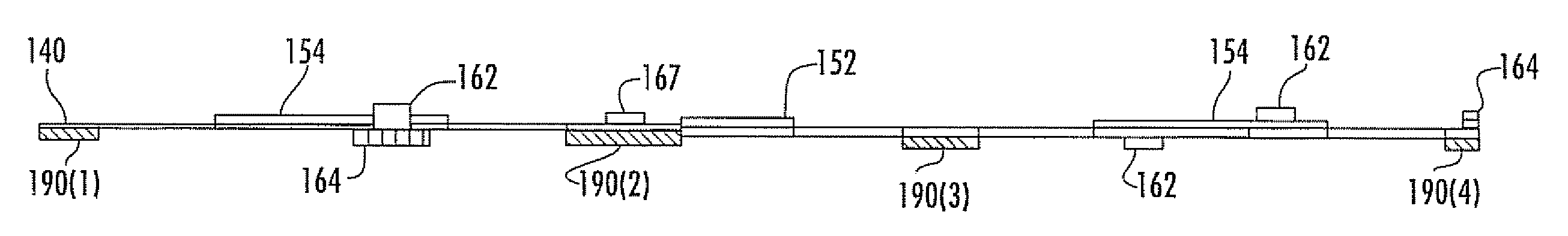
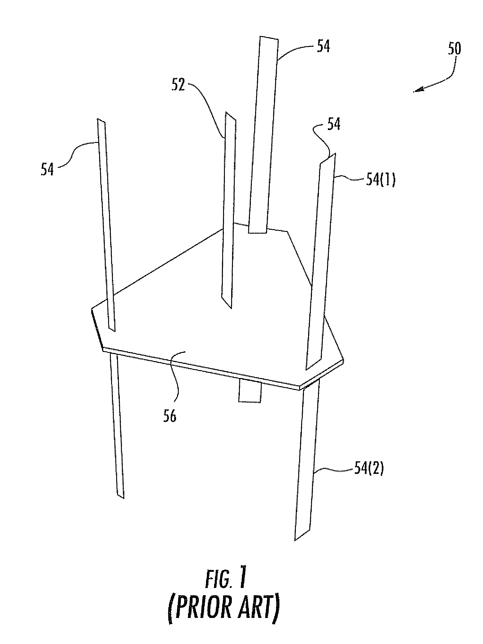
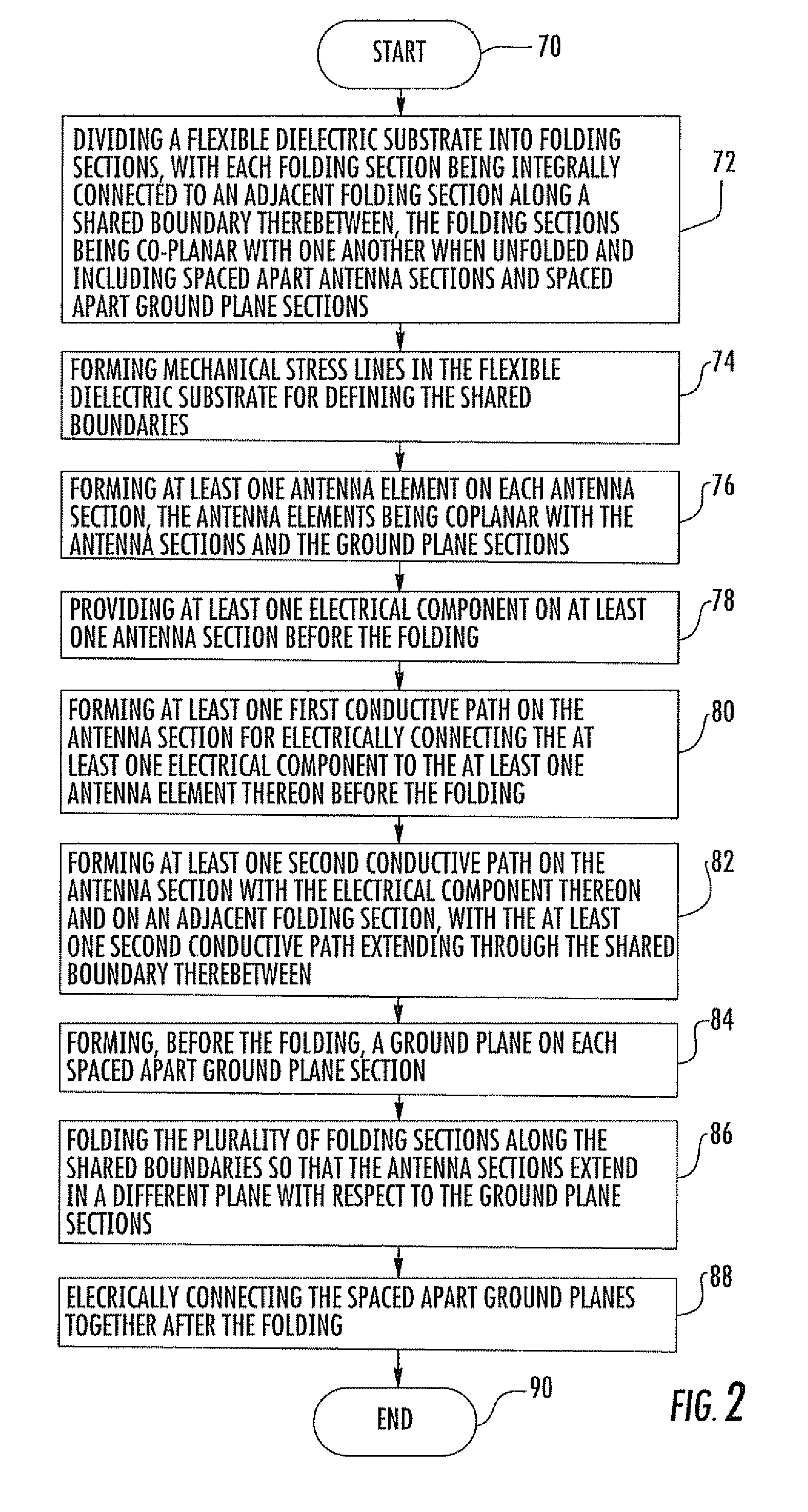
[0026] In accordance with the present invention, the parts for a three-dimensional antenna array are initially formed as a two-dimensional structure. The two-dimensional structure is then folded into its final three-dimensional relative positions, and secured in that form. For purposes of illustrating the present invention, the antenna array 50 shown in FIG. 1 will initia...


PUM


Abstract

A method for making an antenna array includes dividing a flexible dielectric substrate into a plurality of folding sections, with each folding section being integrally connected to an adjacent folding section along a shared boundary therebetween. The folding sections are co-planar with one another when unfolded and include spaced apart antenna sections, spaced apart ground plane sections and connecting sections therebetween. An antenna element is formed on each antenna section. The antenna elements are coplanar with the antenna sections, the ground plane sections and the connecting sections. The folding sections of the flexible dielectric substrate are folded along the shared boundaries so that the antenna sections extend in a different plane with respect to the ground plane sections.

Description

RELATED APPLICATION [0001] This application claims the benefit of U.S. Provisional Application Ser. No. 60 / 651,608 filed Feb. 10, 2005, the entire contents of which are incorporated herein by reference.FIELD OF THE INVENTION [0002] The present invention relates to the field of antennas, and more particularly, to a method for making a three-dimensional antenna array using two-dimensional structures. BACKGROUND OF THE INVENTION [0003] Antenna arrays for advanced applications are often constructed in a three-dimensional configuration. Example antenna arrays include beam forming antennas having three or more antenna elements and MIMO antenna arrays. An example three-dimensional antenna array 50 is illustrated in FIG. 1. The antenna array 50 includes an active center antenna element 52, and three passive antenna elements 54 extending outward from a dielectric substrate 56. The passive antenna elements 54 include upper and lower conductive segments 54(1) and 54(2). [0004] The cost to indi...

Claims


Application Information

Patent Timeline
Patent Type & Authority Applications(United States)
IPC IPC(8): H01Q1/38
CPCH01Q1/38
Inventor GOLDBERG, STEVEN J.
Owner INTERDIGITAL TECH CORP
Why Eureka
Try Eureka