Overmold material and metal base interface design for leakage reduction in a disc drive

a technology of overmolding material and metal base, which is applied in the direction of casings/cabinets/drawers, instruments, casings/cabinets/drawers, etc., can solve the problems of filter holder and actuator crash stop difficulties, and achieve the effect of facilitating, and minimizing the passage of air

Inactive Publication Date: 2006-08-24
SEAGATE TECH LLC
View PDF9 Cites 2 Cited by
  • Summary
  • Abstract
  • Description
  • Claims
  • Application Information

AI Technical Summary

Benefits of technology

[0007] The present invention generally relates to a base for use in a disc drive. The base has an interior and an exterior surface relative to the disc drive, and there is an entrance hole or opening passing between the two surfaces. A groove surrounding the entrance hole and minimizes the passage of air from the exterior surface to the interior surface. The groove may be in the shape as desired. The base is generally made of stamped or machined metal, and the overmold material generally made of a moldable material. The groove is amenable to the stamping process as well.
[0008] In another embodiment, an additional groove surrounds the first groove, which further minimizes the passage of air between the exterior and the interior of the disc drive. Further embodiments include a plurality of grooves extending around the first groove for further minimizing air flow into the interior of the disc drive. Further refinements can be made to the present invention, including the use of a groove with different shapes.

Problems solved by technology

One of the difficulties in meeting such a small form factor is the formation of the base of the microdrive that provides support for the components of the disc drive and which also prevents contamination from reaching the inside of the disc drive.
However, other more detailed features such as the mounting slot, the filter holder and actuator crash stops are difficult to make by this process alone, especially given more stringent form factor requirements of small designs.

Method used


Image

  • Overmold material and metal base interface design for leakage reduction in a disc drive
  • Overmold material and metal base interface design for leakage reduction in a disc drive
  • Overmold material and metal base interface design for leakage reduction in a disc drive

Examples


Embodiment Construction

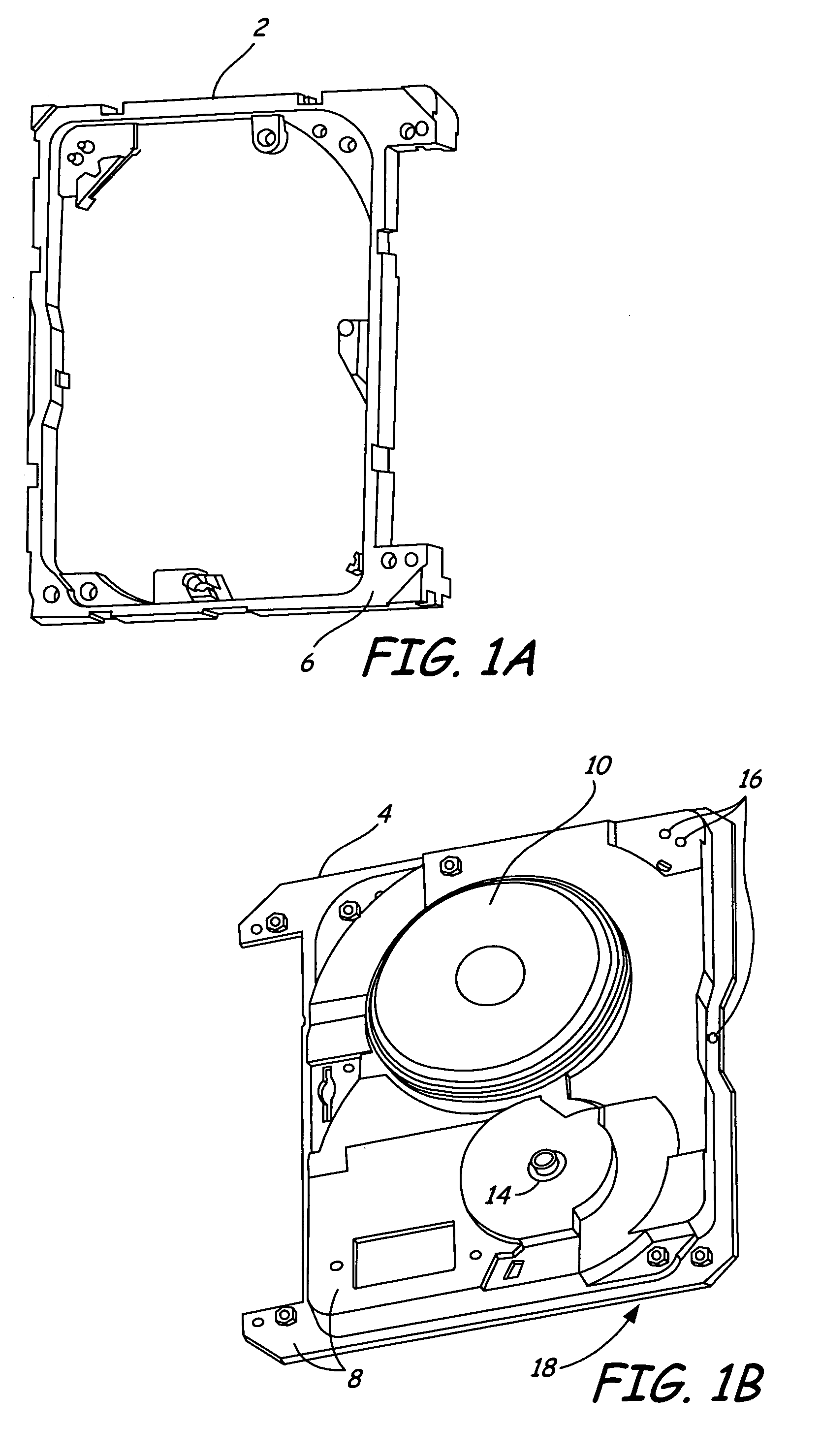
[0020]FIGS. 1A and 1B show two portions of a prior art overmolded stamped base: an overmolded plastic portion 2 and a stamped metal base portion 4. Each of the portions 2 and 4 have an upper surface 6 and 8, respectively. (Plastic portion 2 and base 4 are separated here for clarity, but in practice are positioned closely adjacent to each other once overmolding is complete.) Other components of the disc drive are mounted on base portion 4; a plateau section 10 is formed in base 4 to support at least one disc (not shown), and a central hole 12 is formed in base 4 to allow a motor spindle (not shown) to be inserted through base 4. Another mounting hole 14 is provided to install a swing arm (not shown). The swing arm transports a head sensor of the disc drive and permits it to rapidly move in an arc across the surface of the disc.

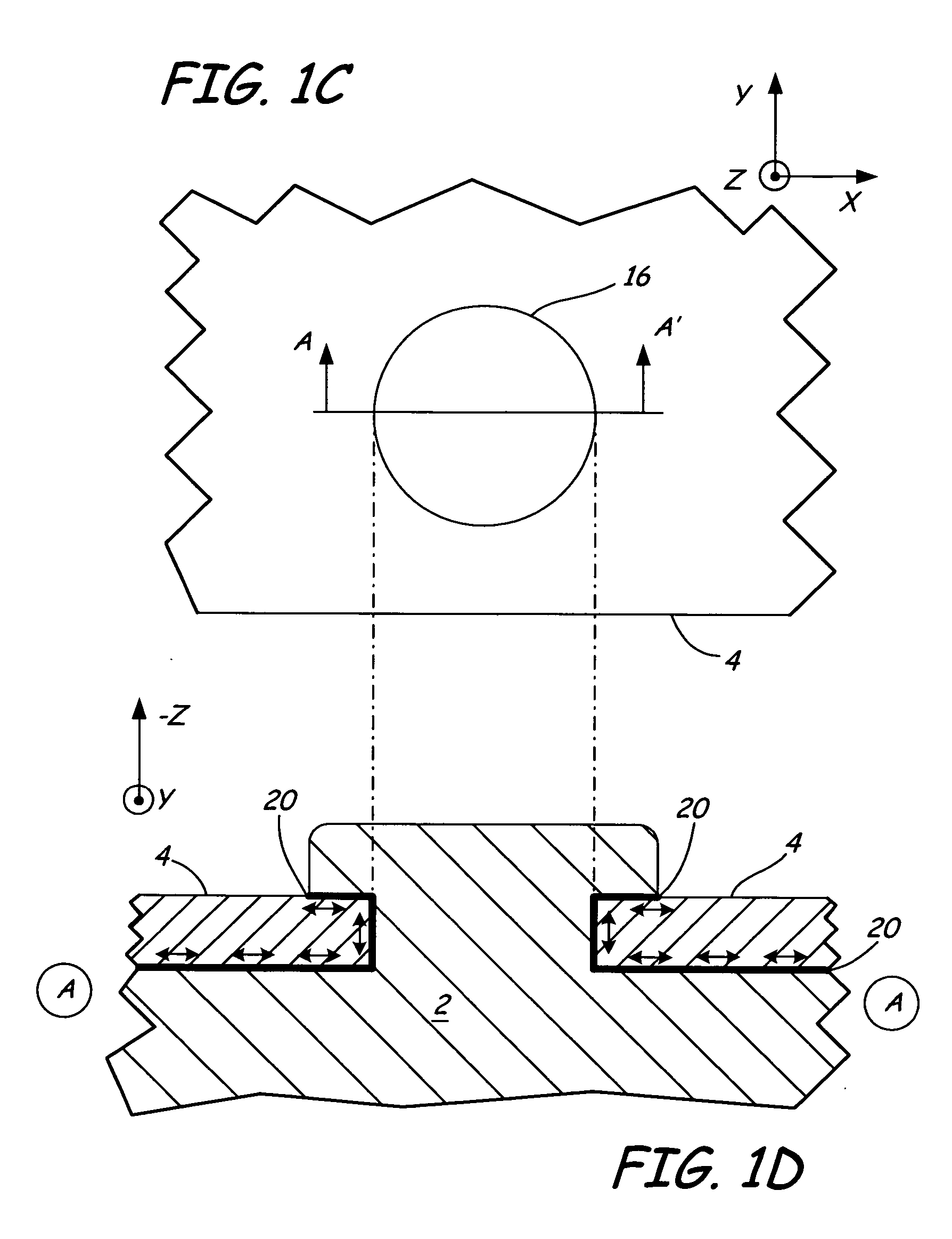
[0021] In an overmolding process, a mold is positioned over and in contact with surface 8 of base 4 and from an underside 18 of base 4, liquid material such a...


PUM

PropertyMeasurementUnit
obtuse angleaaaaaaaaaa
trapezoid shapeaaaaaaaaaa
speedaaaaaaaaaa

Abstract

A base plate of a disc storage system including an interior and an exterior surface, an entrance hole passes between the two surfaces and a groove surrounds the entrance hole and reduces the passage of air along an interface between the exterior and the interior surfaces. The groove may be in the shape of a circle or other alternative shapes such as a rectangle, as considered within the plane of the interior surface. An overmold is molded to the base plate and fills the groove. The plate is generally made of a plastic. The groove is amenable to the stamping process as well.

Description

FIELD OF THE INVENTION [0001] The present invention relates generally to disc drive storage devices, and more particularly, but not by limitation, to a base for disc drive storage. BACKGROUND OF THE INVENTION [0002] Disc drives are commonly used in work stations, personal computers, portable computers, and other computer systems to store large amounts of data in a form that can be made readily available to a user. In general, a disc drive comprises one or more magnetic discs that are rotated by a spindle motor at a constant high speed. A transducer is used to write and / or read back information from the surface of a disc. [0003] Continued demand exists for higher disc drive performance from disc drives having smaller form factors. Such demands require increases in spindle motor rotation speeds, increases in areal density recording capabilities, and faster data access times, along with decreases in the size of the disc drive components and the housing that encloses them. Standard disc...

Claims


Application Information

Patent Timeline
Patent Type & Authority Applications(United States)
IPC IPC(8): G11B17/00
CPCG11B25/043
Inventor XU, MOKOONG, JOHNAN SJHONG, YIRENLIM, POHLYE
Owner SEAGATE TECH LLC
Why Eureka
Try Eureka