
Laser generator

a laser generator and laser technology, applied in the direction of active medium materials, manufacturing tools, optical resonator shape and construction, etc., can solve the problems of lowering the power of the generator and damaging the optical components seriously, the method does not sufficiently protect components, and the optical components are not yet sufficiently protected, so as to achieve stable laser output, effective expulsion of air containing impurities, and enhanced reliability

Active Publication Date: 2006-08-24
PANASONIC CORP
View PDF5 Cites 3 Cited by
  • Summary
  • Abstract
  • Description
  • Claims
  • Application Information

AI Technical Summary

Benefits of technology

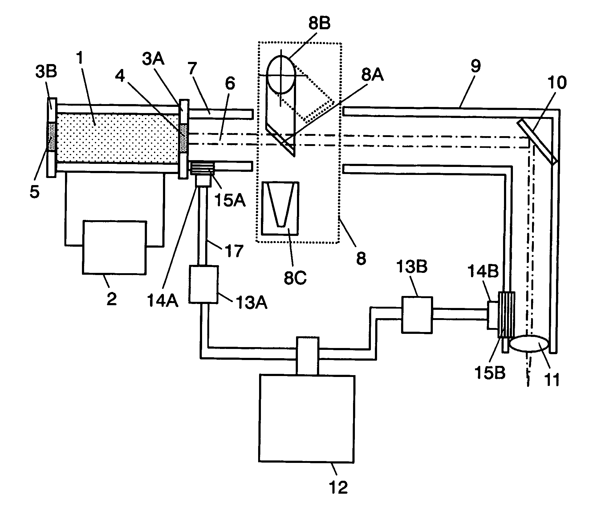
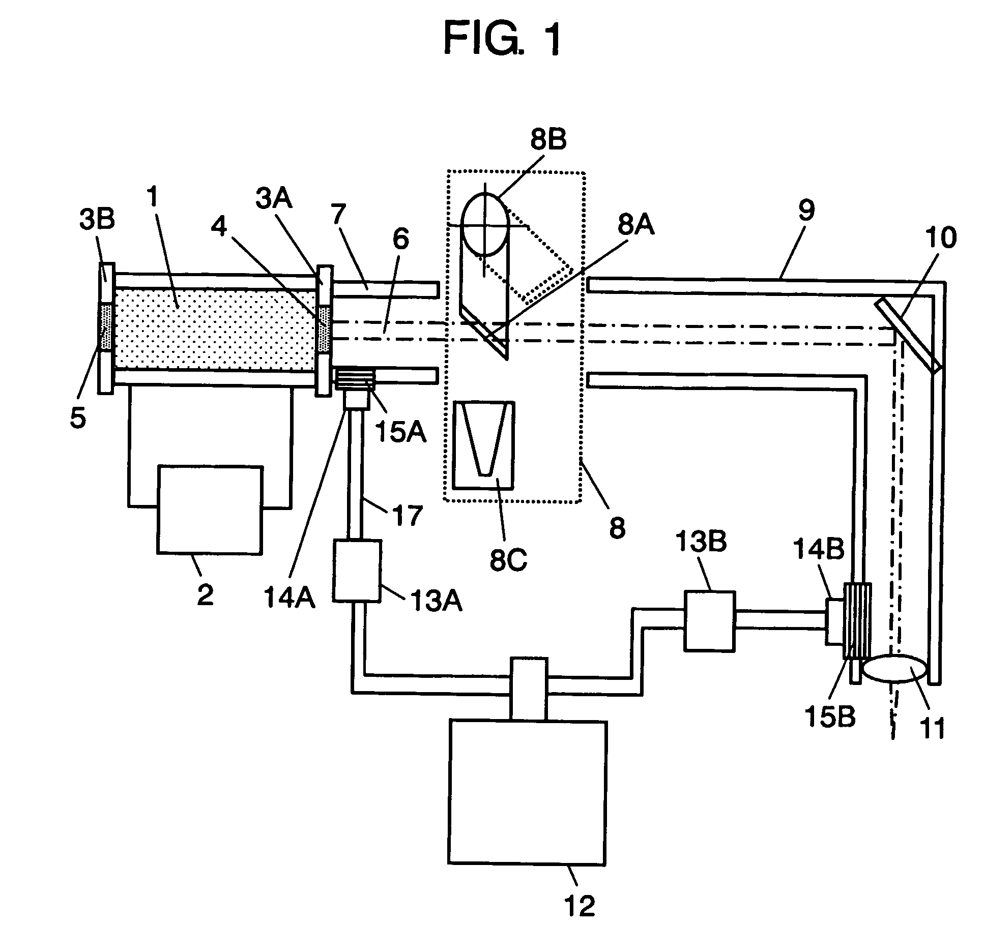
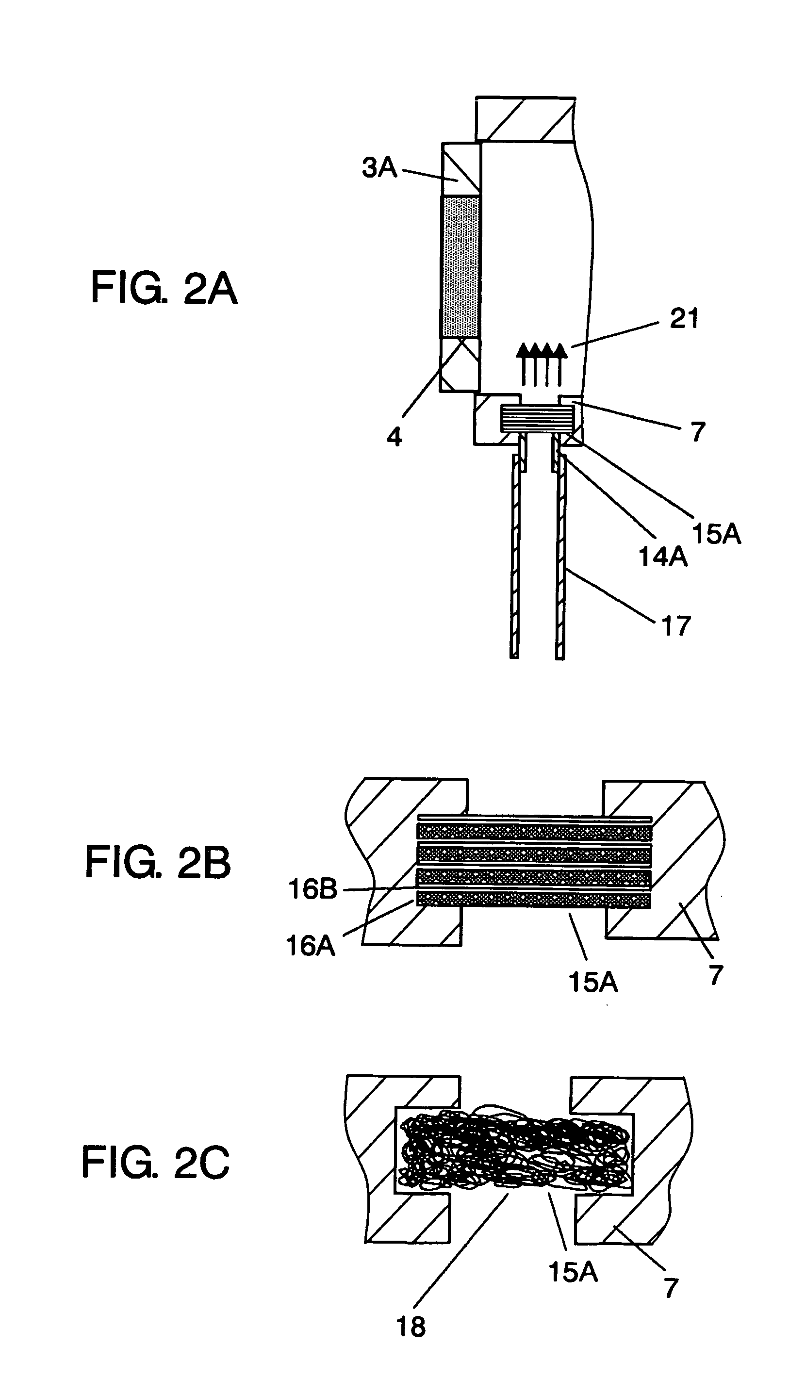
[0010] A laser generator of the present invention has a laser generating part, a laser-introducing duct, a light path duct, and a condensing lens. The laser generating part includes a mirror outputting a laser light. The laser-introducing duct guides the laser beam output by the laser generating part. The light path duct is installed next to the laser-introducing duct and guides the laser beam. The condensing lens is placed at an exit of the light path duct and condenses the laser beam. The laser generator has at least one of a pair of first gas introducing part and a first flow laminator, and a pair of second gas introducing part and a second flow laminator. The first gas introducing part is placed near the mirror at the laser-introducing duct and introduces gas into the laser-introducing duct. The first flow laminator is placed at the first gas introducing part and regulating flow of the gas. The second gas introducing part is placed near the condensing lens at the light path duct and introduces the gas into the light path duct. The second flow laminator is placed at the second gas introducing part and regulates flow of the gas. According to the constitution, gas supplied to the laser-introducing duct and light path duct is laminated, effectively expelling out air containing impurities. Therewith, impurities on the surfaces of the output mirror and the condensing lens are reduced to a minimum level, providing the laser generator having a stable laser output and an enhanced reliability.

Problems solved by technology

If the air containing such impurities flows into the light path of the components and attaches to surfaces of the mirrors and lens 41, the laser light may burn the surfaces, which causes lowering power of the generator and damaging the optical components seriously.
Thus, the method does not sufficiently protect components i.e. the mirrors and the lens that are very sensitive to dust, oil and other attached impurities, from performance deterioration caused by the impurities.
However, the optical components are not yet sufficiently protected from being contaminated so achievement of the high power of the laser is obstructed.

Method used


Image

  • Laser generator
  • Laser generator
  • Laser generator

Examples


Embodiment Construction

[0016]FIG. 1 is a constitutional drawing explaining a structure of a laser generator according to an exemplary embodiment of the present invention.

[0017] In the laser generator, power supply 2 excites laser medium 1. Translucent mirror (hereinafter, mirror) 4 and laser light amplifying mirror (hereinafter, mirror) 5 oscillate a caused light, generating laser beam 6. Mirror holder 3A and 3B hold mirror 4 and mirror 5, respectively. Because mirror 4 is a translucent mirror, the laser beam is allowed to be output to outside. FIG. 1 illustrates only one laser light amplifying mirror, but two or more of the mirrors can be installed. Laser medium 1, power supply 2, and mirrors 4 and 5 constitute a laser generating part.

[0018] Laser beam, amplified by mirrors 4 and 5 and output through mirror 4, passes through inside laser-introducing duct (hereinafter, duct) 7 that protects the laser beam. In other words, duct 7 directs the laser beam output by the laser generating part to outside. The ...


PUM

PropertyMeasurementUnit
mesh sizeaaaaaaaaaa
pressureaaaaaaaaaa
translucentaaaaaaaaaa

Abstract

Flow laminators are attached to gas introducing parts installed in a laser generator preventing impurities from attaching to surfaces of a translucent mirror and a condensing lens. The flow laminators prevent airflow from producing a turbulent flow and air on the surface of the mirror and the lens are cleaned up, therewith reducing attachment of impurities further.

Description

TECHNICAL FIELD [0001] The invention relates to a laser generator exciting laser medium, amplifying a caused light with light amplifying mirrors, and outputting a laser beam through one of the light amplifying mirrors as a translucent mirror. BACKGROUND ART [0002]FIG. 3 is a constitutional drawing of a conventional laser generator. In the laser generator, power supply 32 excites laser medium 31. Translucent mirror (hereinafter, called mirror) 34 and laser light amplifying mirror (hereinafter, mirror) 35 oscillate a caused light to be generated as laser beam 36. Mirror holder 33A and 33B hold mirrors 34 and 35, respectively. Mirror 34 is a translucent mirror allowing the laser beam to be output to outside. Mirror 34 is generally called an output mirror. [0003] Laser beam 36 which is amplified by mirrors 34 and 35 and output through mirror 34 to outside passes through inside laser introducing duct (hereinafter, duct) 37 that protects the laser beam, shutter unit (hereinafter, shutter)...

Claims


Application Information

Patent Timeline
Patent Type & Authority Applications(United States)
IPC IPC(8): H01S3/08H01S3/13H01S3/00B23K26/12B23K26/16
CPCB23K26/12B23K26/14B23K26/1476B23K26/16B23K26/128
Inventor HAJI, NOBUYUKIEGUCHI, SATOSHIYAMAMOTO, ATSUKISHINNO, NOBUO
Owner PANASONIC CORP
Learn More