Laser beam generation device and laser processing apparatus including the same
- Summary
- Abstract
- Description
- Claims
- Application Information
AI Technical Summary
Benefits of technology
Problems solved by technology
Method used
Image
Examples
first embodiment
[0062]
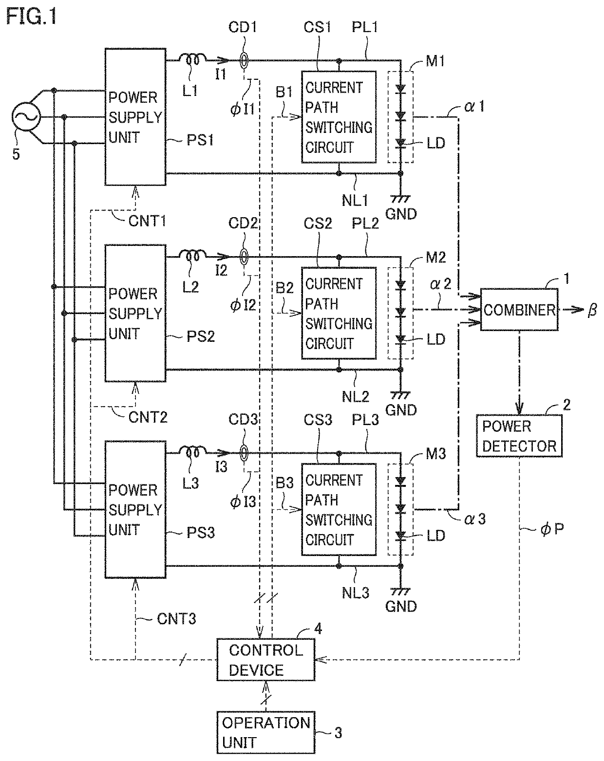
[0063]FIG. 1 is a circuit block diagram illustrating a configuration of a laser beam generation device according to a first embodiment. In FIG. 1, the laser beam generation device includes a plurality of (three in this example) power supply units PS1 to PS3, a plurality of reactors L1 to L3, a plurality of DC positive buses PL1 to PL3, a plurality of DC negative buses NL1 to NL3, current detectors CD1 to CD3, a plurality of current path switching circuits CS1 to CS3, a plurality of LD modules M1 to M3, a combiner 1, a power detector 2, an operation unit 3, and a control device 4.
[0064]Positive electrodes of power supply units PS1 to PS3 are connected to one terminals of reactors L1 to L3, respectively. The other terminals of reactors L1 to L3 are connected to one ends of DC positive buses PL1 to PL3, respectively. The other ends of DC positive buses PL1 to PL3 are connected to anode terminals of LD modules M1 to M3, respectively.
[0065]Cathode terminals of LD modules M1 to M3 a...
second embodiment
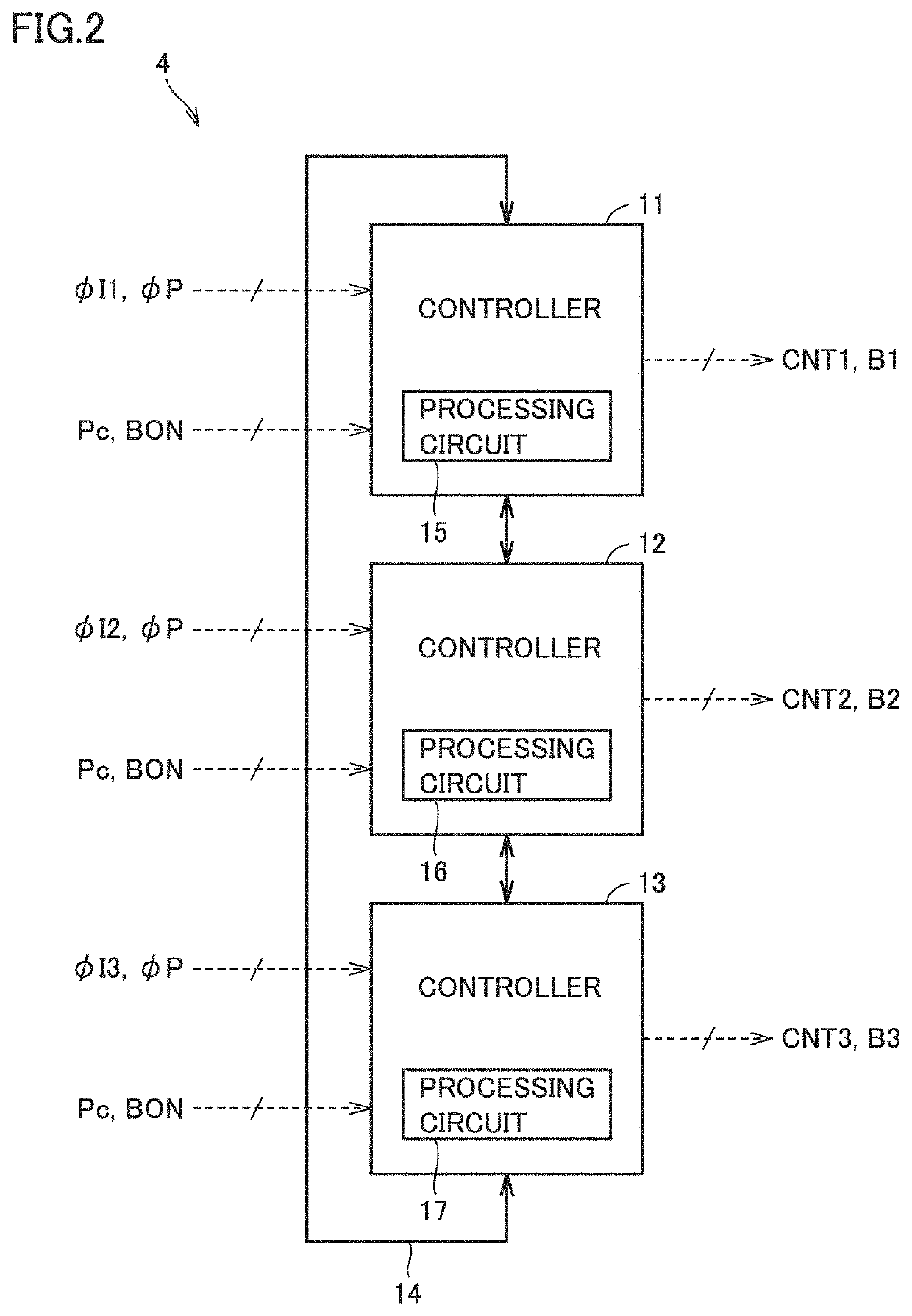
[0217]FIG. 16 is a block diagram illustrating a main part of a laser beam generation device according to a second embodiment and is a view compared with FIG. 2. Referring to FIG. 16, the laser beam generation device is different from that of the first embodiment in that phase angles β1 to β3 of control signals CNT1 to CNT3 can be set using operation unit 3, and that set phase angles β1 to β3 are provided to controller 11 to 13, respectively.
[0218]The user of the laser beam generation device operates operation unit 3 to set phase angles β1 to β3 of control signals CNT1 to CNT3 in addition to laser output setting value Pc and the waveform of beam-on signal BON. Each of phase angles θ1 to θ3 may be a constant value or a value that changes in synchronization with beam-on signal BON. The waveform of beam-on signal BON, laser output setting value Pc, and phase angles θ1 to 743 are stored in the storage (not illustrated) in operation unit 3.
[0219]For example, when the user of the laser bea...
third embodiment
[0228]FIG. 19 is a block diagram illustrating a main part of a laser beam generation device according to a third embodiment and is a view compared with FIG. 16. Referring to FIG. 19, the laser beam generation device is different from that of the second embodiment in that frequencies f1 to f3 of control signals CNT1 to CNT3 can be set using operation unit 3, and that set frequencies f1 to f3 are provided to controller 11 to 13, respectively.
[0229]The user of the laser beam generation device operates operation unit 3 to set frequencies f1 to f3 of control signals CNT1 to CNT3 in addition to laser output setting value Pc and the waveform of beam-on signal BON. Each of the frequencies f1 to f3 may be a constant value or a value that changes in synchronization with beam-on signal BON. The waveform of beam-on signal BON, laser output setting value Pc, and frequencies f1 to f3 are stored in the storage (not illustrated) in operation unit 3.
[0230]For example, when the user of the laser beam...
PUM
| Property | Measurement | Unit |
|---|---|---|
| Angle | aaaaa | aaaaa |
| Temperature | aaaaa | aaaaa |
| Power | aaaaa | aaaaa |
Abstract
Description
Claims
Application Information
 - R&D
- Intellectual Property
- Life Sciences
- Materials
- Tech Scout
- Unparalleled Data Quality
- Higher Quality Content
- 60% Fewer Hallucinations
Browse by: Latest US Patents, China's latest patents, Technical Efficacy Thesaurus, Application Domain, Technology Topic, Popular Technical Reports.
© 2025 PatSnap. All rights reserved.Legal|Privacy policy|Modern Slavery Act Transparency Statement|Sitemap|About US| Contact US: help@patsnap.com


