Object information acquiring apparatus and laser apparatus

Inactive Publication Date: 2015-01-15
CANON KK
View PDF10 Cites 5 Cited by
  • Summary
  • Abstract
  • Description
  • Claims
  • Application Information

AI Technical Summary

Benefits of technology

The patent describes a photoacoustic biological diagnosis apparatus and a laser apparatus. The laser apparatus is used to generate laser pulses for the diagnosis apparatus. The patent also includes diagrams of the configurations of the apparatus and control timings for the laser apparatus. Additionally, the patent provides a diagram of the configuration of the photoacoustic biological diagnosis apparatus. The technical effects of this patent include better diagnosis of biological samples through the use of laser technology, improved control over the laser beam for accuracy, and improved accuracy of photoacoustic diagnosis through the use of multiple laser pulses.

Problems solved by technology

The flash lamp excited laser has difficulty in keeping the laser output in a constant state.
That is, a change in the voltage applied to the flash lamp fluctuates the thermal lens to make the output intensity unstable.
That is, a new challenge is to control the output so as to keep the thermal lens of the resonator constant at two different wavelengths.

Method used


Image

  • Object information acquiring apparatus and laser apparatus
  • Object information acquiring apparatus and laser apparatus
  • Object information acquiring apparatus and laser apparatus

Examples


example 1

[0076]An example of the present invention will be illustrated. In this case, an example of a method for controlling a flash lamp excited pulse laser will be illustrated.

[0077](Apparatus Configuration)

[0078]In Example 1, an alexandrite laser was used as a light source. However, the light source used in the present invention is not limited to the alexandrite.

[0079]The laser apparatus is configured such that a wavelength of 795 nm and a wavelength of 755 mm oscillate. Repetition frequency is 20 Hz.

[0080]FIG. 4 shows a configuration of a resonator including an alexandrite laser. A flash lamp 402 that excites alexandrite and an alexandrite crystal 401 are arranged in an excitation chamber 400. The alexandrite crystal is immersed in circulating water at 75° C. An optical thin film is applied to an output mirror 403 so that reflectance is 72% for the wavelength of 795 nm and 42% for the wavelength of 755 nm. A dielectric reflection film that significantly reflects a center wavelength of 75...

example 2

[0090]In Example 2, a photoacoustic measurement procedure will be illustrated which uses a flash lamp excited laser apparatus. In Example 2, particularly the measurement step will be described in detail with reference to a flowchart in FIG. 7.

[0091](Apparatus Configuration)

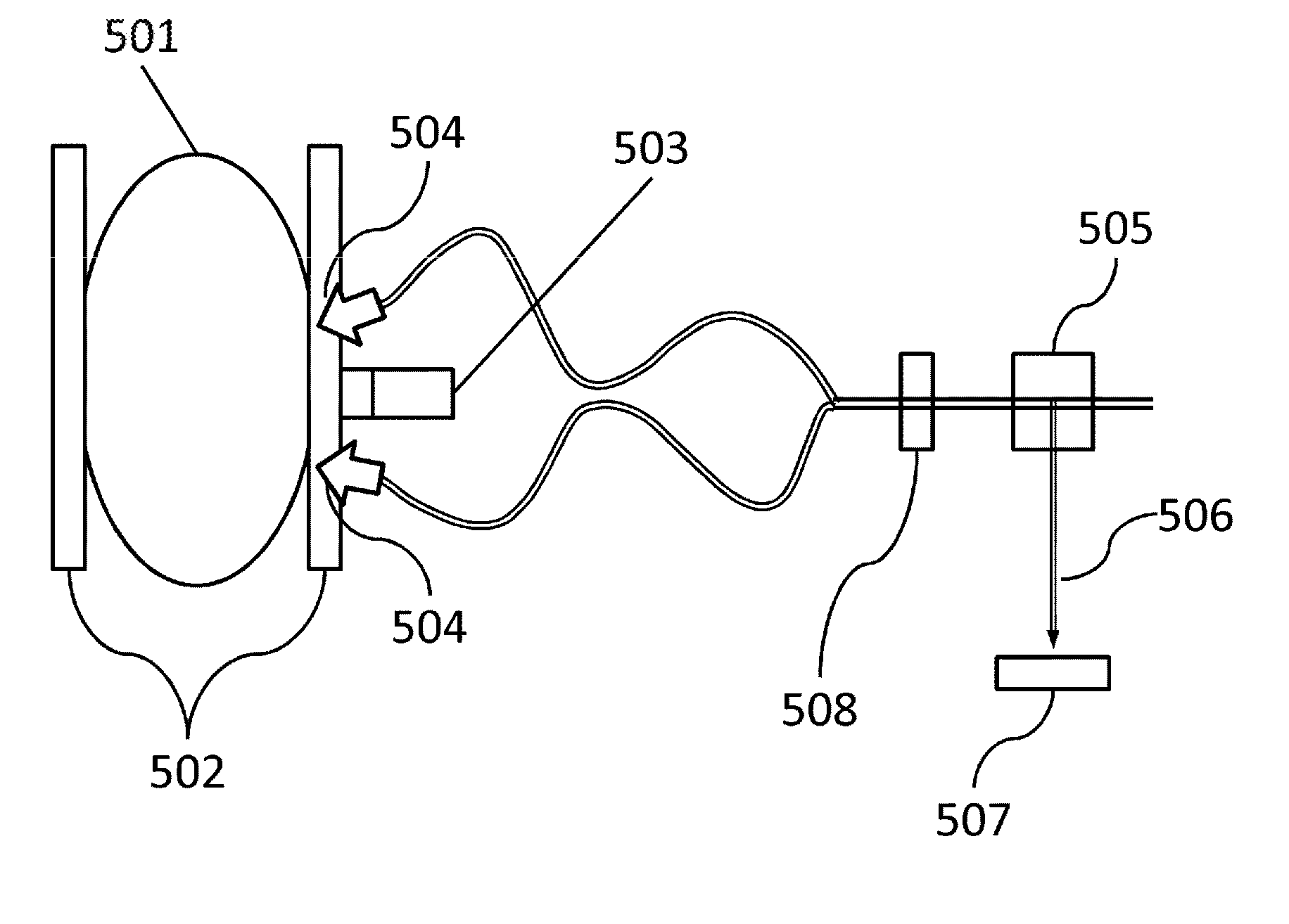
[0092]An apparatus in FIG. 5 was used as a photoacoustic biological diagnosis apparatus. This apparatus can measures a relatively large biological segment such as the breast. In Example 2, instead of the living body, a phantom 501 was measured which included an absorbent embedded therein and simulating a blood vessel equivalent to an oxygen saturation of 80%.

[0093]The phantom 501 is lightly pressed between approximately parallel flat plates 502, to fix a measurement segment. Illumination units 504 are provided at the respective opposite sides of an ultrasound probe 503 so as to serve as output ends for laser light. Measurement is performed with a scanner, not shown in figures, by simultaneously scanning the ultras...


PUM


Abstract

An object information acquiring apparatus has: a resonator including at least a laser medium, a flash lamp that excites the laser medium, and an output mirror that outputs laser light; an oscillator that oscillates the laser light; a controller that controls a timing at which the oscillator oscillates the laser light after excitation performed by the flash lamp is started; a selector that selects a wavelength of the laser light; a probe that detects an acoustic wave generated in an object; and a processor that acquires characteristic information on the object, wherein the controller determines the timing, at which the laser light is oscillated, for each of the wavelengths in such a manner that a difference in output energy of the laser light falls within a predetermined range.

Description

BACKGROUND OF THE INVENTION[0001]1. Field of the Invention[0002]The present invention relates to an object information acquiring apparatus and a laser apparatus.[0003]2. Description of the Related Art[0004]A technique known as photoacoustic tomography (PAT) is being developed. PAT is a technique for irradiating a measurement segment with pulsed laser light of the order of nanoseconds, receiving a photoacoustic wave generated in the measurement segment using a probe, and processing the resulting receive signal to form an image. PAT enables biological function analysis using spectral measurement based on the absorption coefficient of the biological tissue. For example, the oxidation state of hemoglobin in the blood is considered to be important biological function information.[0005]S. Manohar et al. Proc. of SPIE vol. 6437 643702-1 reports a photoacoustic biological diagnosis apparatus in which a PAT apparatus is applied to observation of a tumor inside the breast. Peripheries of the ...

Claims


Application Information

Patent Timeline
IPC IPC(8): A61B5/00H01S3/11H01S3/13
CPCH01S3/11A61B5/0095H01S3/13A61B5/4312H01S3/115H01S3/092H01S3/061H01S3/1623H01S3/08059H01S3/1306
Inventor ICHIHARA, SHIGERUKOBAYASHI, SHUICHI
Owner CANON KK
Why Eureka
Try Eureka