System for replacement of sheet abrasive

Inactive Publication Date: 2006-08-24
TIMESAVERS
View PDF6 Cites 2 Cited by
  • Summary
  • Abstract
  • Description
  • Claims
  • Application Information

AI Technical Summary

Problems solved by technology

Without the foam, unwanted scratches would res

Method used


Image

  • System for replacement of sheet abrasive
  • System for replacement of sheet abrasive
  • System for replacement of sheet abrasive

Examples


Embodiment Construction

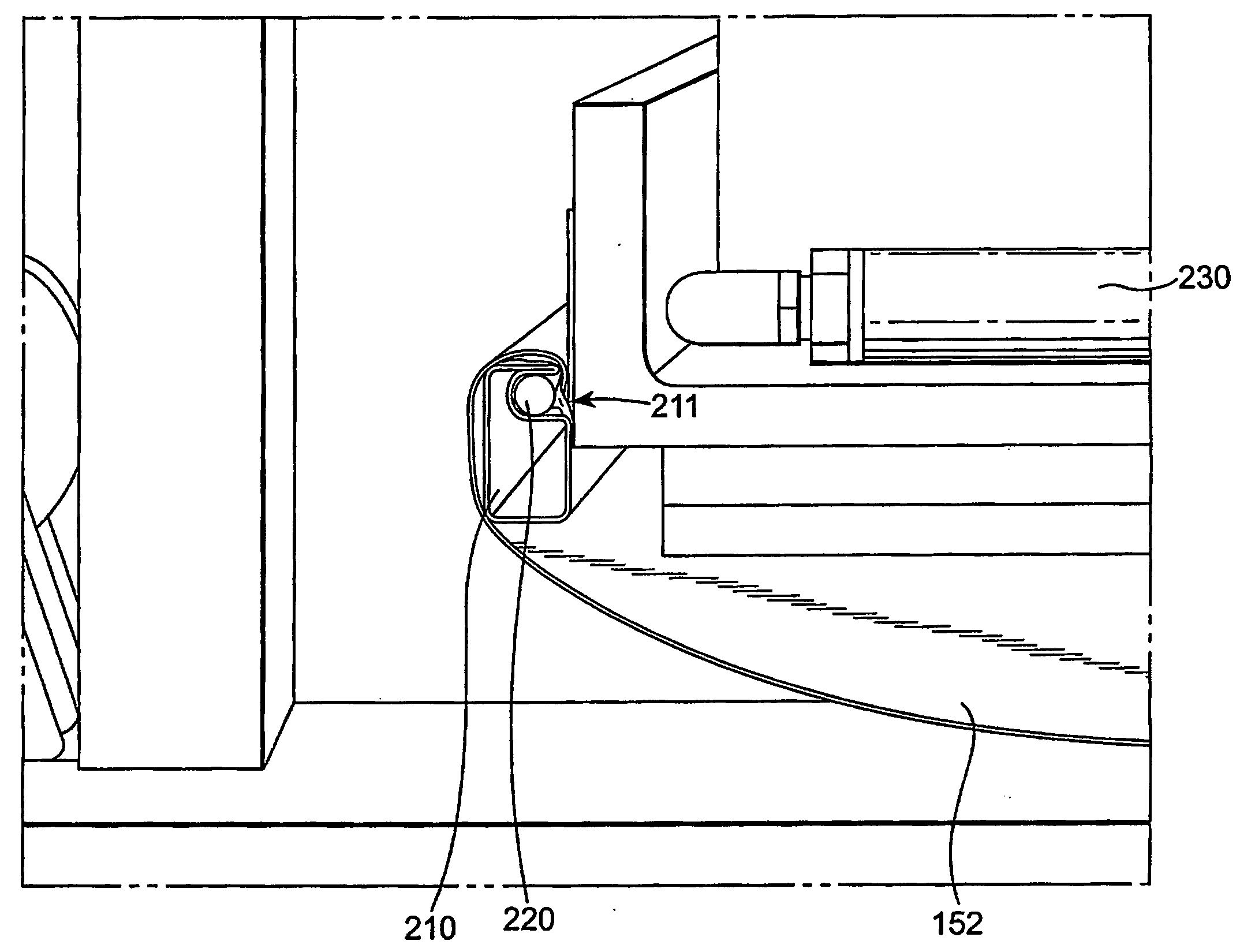
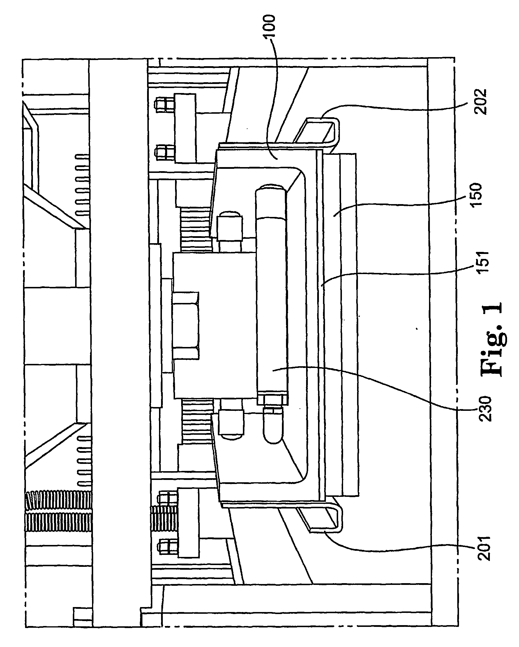
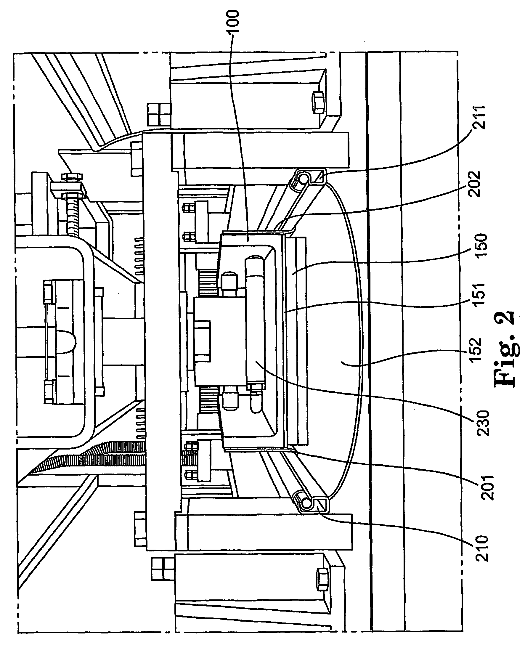
[0013]FIG. 1 shows that platen 100 of a surface finishing machine is constructed so that pad 150 is somewhat permanently mounted to platen 100 by any convenient means. “Somewhat permanently” refers to the preferred embodiment, in which pad 150 is mounted to a plate 151, which in turn is connected to platen 100 in any conventional manner. Thus, plate 151 may be removed only when it is necessary to replace pad 150, which is not required as frequently as it is may be necessary or desirable to replace the abrasive material, as described below, and platen 100 need not be removed from the apparatus at all (unless that is the most convenient way to replace pad 150 and plate 151).

[0014] Platen 100 further comprises rails 201 and 202, at least one of which is moveably and adjustably mounted to the sides of platen 100 so that its longitudinal position with respect to their respective sides of platen 100 may be adjusted by any convenient means. (In this and the other figures, the longitudinal...


PUM


Abstract

A system for rapid replacement of abrasive in machinery which uses the abrasive to finish the surfaces of workpieces that pass through the machinery on a belt, such as so-called widebelt sanders. One preferred embodiment of the system employs an abrasive material that is frictionally held on each edge to mounts. The position of the mounts may be varied to increase or decrease the tension of abrasive material against the working surface of the platen, that the assembly may be removed from the apparatus. In another embodiment, the abrasive material is formed with integral, permanent mounts on the edges of the abrasive material, so that the entire combination may be supplied or replaced as a unit. A variety of configurations of mounts may be used.

Description

CROSS-REFERENCE TO RELATED APPLICATION [0001] This application claims the benefit of provisional application No. 60 / 461,392 filed Apr. 8, 2003.TECHNICAL FIELD [0002] This invention relates to systems for rapid replacement of abrasive in machinery which uses the abrasive to finish the surfaces of workpieces that pass through the machinery on a belt, such as so-called widebelt sanders. BACKGROUND [0003] The basic features of surface finishing machines of the type that represent the preferred environment for the invention are shown in at least the following U.S. Patents, the entire contents of which are incorporated into reference, and a copy of which is enclosed as if fully set forth in the text of this document: U.S. Pat. No. 5,081,794 (Haney); U.S. Pat. No. 5,181,342 (Haney); U.S. Pat. No. 5,321,913 (Haney); U.S. Pat. No. 5,443,414 (Haney); U.S. Pat. No. 5,702,287 (Haney); U.S. Pat. No. 5,707,273 (Grivna); U.S. Pat. No. 4,473,500 (David); U.S. Pat. No. 4,837,984 (David); and U.S. Pa...

Claims


Application Information

Patent Timeline
IPC IPC(8): B24B21/00B24B21/18B24B41/00
CPCB24B21/18B24B41/00B24B45/00
Inventor ANDERSON, THOMAS M.
Owner TIMESAVERS
Why Eureka
Try Eureka