Pressure activated IV set

a technology of iv set and iv valve, which is applied in the direction of flow monitors, suction devices, intravenous devices, etc., can solve the problems of frequent air trapped in the tubing, serious injury to a patient, and time-consuming process of priming an iv set, and achieve the effect of considerable time saving

Inactive Publication Date: 2006-08-24
BECTON DICKINSON & CO
View PDF11 Cites 9 Cited by
  • Summary
  • Abstract
  • Description
  • Claims
  • Application Information

AI Technical Summary

Benefits of technology

[0021] The valve may have a shape similar to the shape of the sealing orifice to facilitate closing the sealing orifice. For example, the valve may have a rounded or beveled engagement surface for abutting and closing the sealing orifice. In some configurations, the valve may also include a flexible engagement surface that facilitates the sealing of the valve against the sealing orifice. Thus, the valve may include an elastomeric surface for providing a tight seal against the sealing orifice.
[0035] The method may also include the steps of disposing the remote end of the tube proximate to the drip chamber and preferably, near the operable liquid height of the drip chamber. In configurations where the IV set includes an air vent, the method also include the steps of venting air from the drip chamber and preventing air from exiting the air vent when the height of the liquid within the drip chamber reaches the height of the air vent. To prevent air from reaching a patient when the IV bag or bottle is empty, the method may also include the step of moving the valve against the sealing orifice to prevent the flow of liquid through the pressure activated valve when the head of the liquid within the drip chamber is less than the force of the biasing mechanism.

Problems solved by technology

However, as the liquid flows through the tubing air is frequently trapped in the tubing.
Additionally, if the liquid level is too low, a bubble ladder may form as air is intermittently sucked from the drip chamber into the tubing.
While this concern is critical when accessing allowed to enter a patient's blood stream while receiving the intravenous administration of liquids, the air bubbles can form an air embolism and cause serious injury to a patient.
During this procedure the end of the tubing may contact the waste basket or be touched by the attendant and thus, become contaminated.
Because of the constant supervision and many different steps that may be required to prime an IV set, the priming of an IV set may be a time consuming process.
Additionally, the priming of an IV set can lead to the contamination of the IV set by inadvertently touching a sterile end of the IV set.
An additional concern may arise when the IV bag or bottle begins to run dry.
However, these sensors merely alert the attendant that action is required and do not act to prevent the air from entering the patient.
Additionally, these sensors may be expensive and may require additional training to use.
Alternatively, the floating seal may be inadvertently sucked onto the outlet orifice of the drip chamber before the IV bag or bottle has run dry, preventing the patient from receiving needed liquid and medication.

Method used


Image

  • Pressure activated IV set
  • Pressure activated IV set
  • Pressure activated IV set

Examples


Embodiment Construction

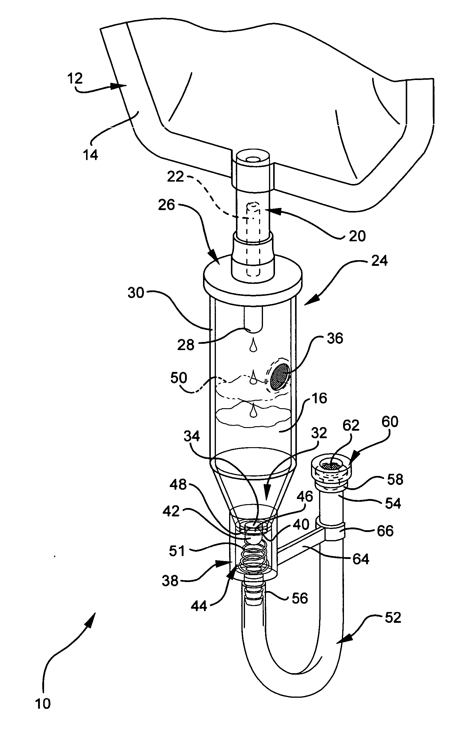
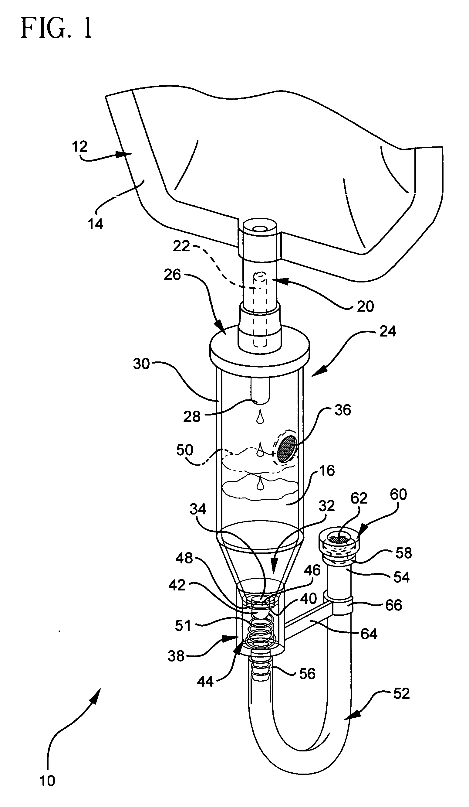
[0043] The presently preferred embodiments of the present invention will be best understood by reference to the drawings, wherein like parts are designated by like numerals throughout. It will be readily understood that the components of the present invention, as generally described and illustrated in the figures herein, could be arranged and designed in a wide variety of different configurations. Thus, the following more detailed description of the embodiments of the IV set of the present invention, as represented in FIGS. 1 through 5, is not intended to limit the scope of the invention, as claimed, but is merely representative of presently preferred embodiments of the invention.

[0044] Referring to FIG. 1, a perspective view illustrates an IV set 10 connected to a source of liquid 12, such as an IV bag 14 containing a liquid 16, by a coupling 20. The coupling 20 may be a spike 22 that is used to puncture the IV bag 14 and access the liquid 16.

[0045] The coupling 20 of the IV set ...


PUM


Abstract

An IV set includes a drip chamber and a pressure activated valve. The drip chamber has an operable liquid height and an outlet orifice. The pressure activated valve is disposed proximate the outlet orifice of the drip chamber and includes a sealing orifice, a valve, and a biasing mechanism. The sealing orifice and the operable liquid height correspond to a head. The biasing mechanism biases the valve against the sealing orifice with a force less than the head of the operable liquid height to control the flow of liquid through the pressure activated valve.

Description

CROSS-REFERENCED RELATED APPLICATIONS [0001] This application claims the benefit of U.S. Provisional Application No. 60 / 654,705, filed Feb. 18, 2005.BACKGROUND OF THE INVENTION [0002] This invention relates generally to tubing sets used in the administration of liquids to a patient that are commonly referred to as intravascular (“IV”) sets and more particularly concerns pressure activated IV sets. An IV set according to the invention is used broadly herein to include tubing sets used in the arterial, intravenous, intravascular, peritoneal, and non-vascular administration of liquid into a patient. Of course, one of skill in the art may use an IV set to administer liquids to other locations within a patient's body than those listed. [0003] Generally, an IV set includes tubing for connecting a patient to a source of liquid. Additionally, an IV set may include a drip chamber connected to the tubing, which is used by a nurse, physician, or other attendant to determine the flow rate of li...

Claims


Application Information

Patent Timeline
Patent Type & Authority Applications(United States)
IPC IPC(8): A61M5/14
CPCA61M1/3626A61M5/1411A61M5/16881A61M5/36A61M39/22A61M39/24
Inventor ADAMS, CHAD M.
Owner BECTON DICKINSON & CO
Why Eureka
Try Eureka