Cleaner for an optical fiber connector

a technology of optical fiber connector and cleaning tape, which is applied in the direction of carpet cleaners, instruments, photosensitive materials, etc., can solve the problems of deterioration in transmission performance, difficult cleaning of communications equipment, and force exerted on cleaning tape, etc., and achieve the effect of quickly restoring dislocated cleaning tap

Inactive Publication Date: 2006-08-31
SEIKOH GIKEN
View PDF2 Cites 38 Cited by
  • Summary
  • Abstract
  • Description
  • Claims
  • Application Information

AI Technical Summary

Benefits of technology

[0010] With the foregoing in view, it is an object of the present invention to provide a cleaner for an optical fiber connector that can swiftly restore dislocated cleaning tape without using a tool.

Problems solved by technology

When such an optical fiber connector is disconnected dust or grease or the like may become attached to the end face of the ferrule of the optical fiber connector causing a deterioration in transmission performance.
A connector to be inserted (a male connector) can be cleaned with relative ease as the end face thereof is exposed, however a connector receiving the male connector (a female connector) incorporated in communications equipment is difficult to clean as the interface requiring cleaning is positioned embedded in a housing.
With this kind of cleaner unnecessary force is exerted on the cleaning tape when the head member is inserted inside the connector housing, for example, as the cleaning tape catches on the housing inner wall and the like.
Accordingly, such cleaners have undesirable problems in terms of operating efficiency and maintenance of the tool.
For example, the arrangement of the tool is required in preparation for the cleaning tape dislocated during a cleaning operation, and it takes a long time to perform the recovery operation using the tool.

Method used


Image

  • Cleaner for an optical fiber connector
  • Cleaner for an optical fiber connector
  • Cleaner for an optical fiber connector

Examples


Embodiment Construction

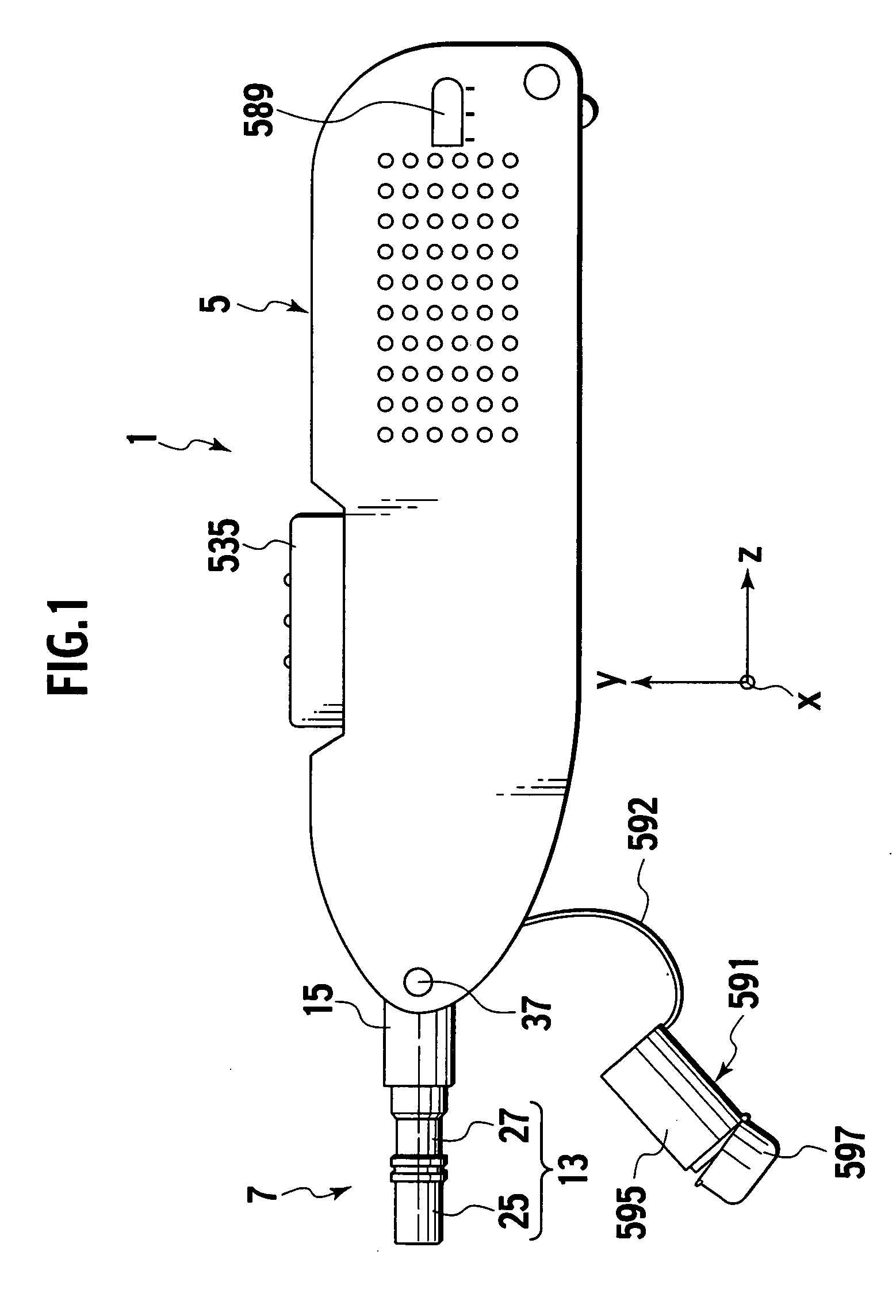
[0033] An embodiment of the present invention will now be described with reference to FIGS. 1 to 11. In these drawings, like reference numerals identify like elements.

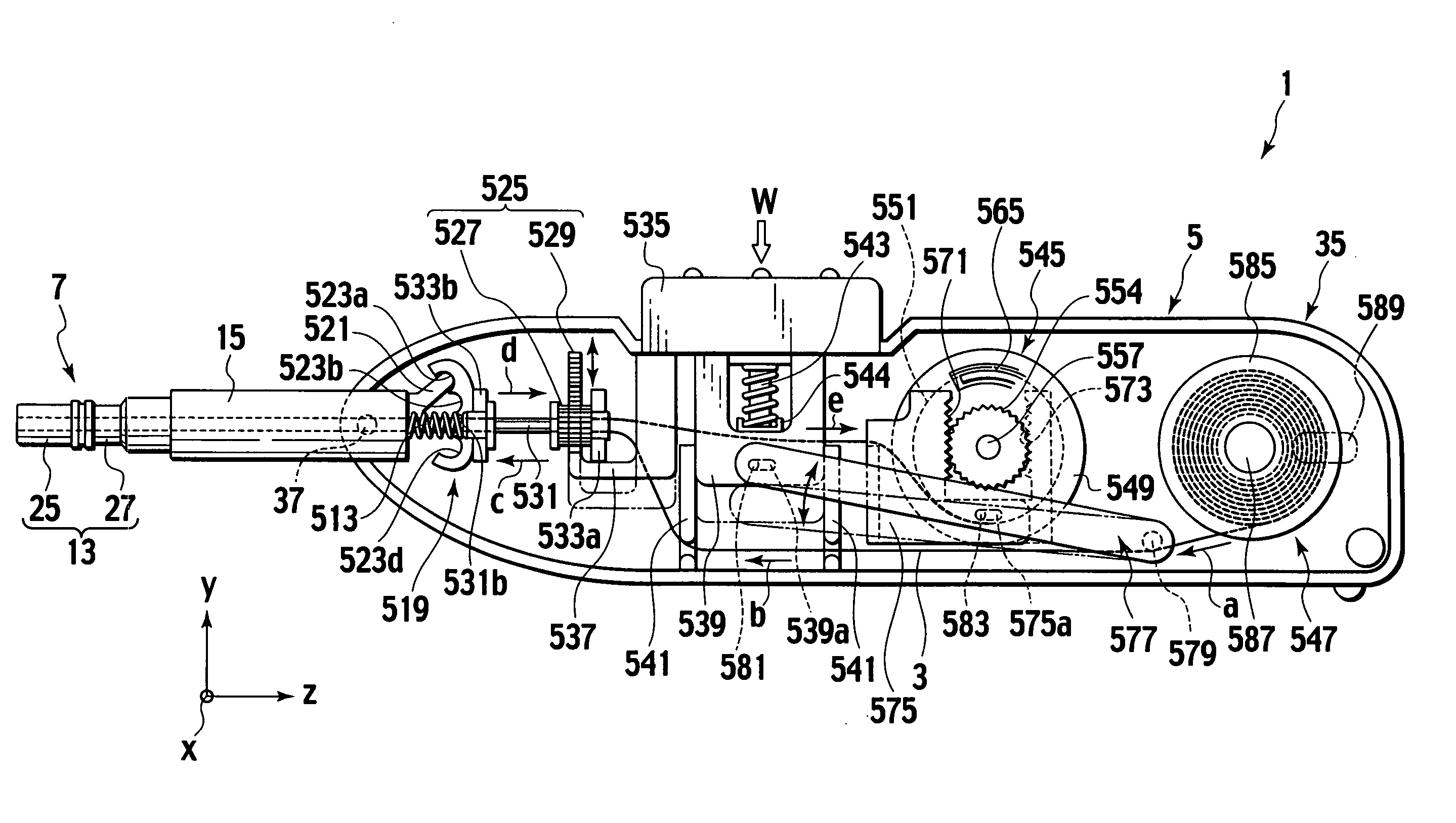
[0034] Referring to FIG. 1, the optical fiber connector cleaner 1 of the present invention, (hereafter “the cleaner”) comprises a housing 5, and a cleaning part 7 disposed at the tip end of the housing 5.

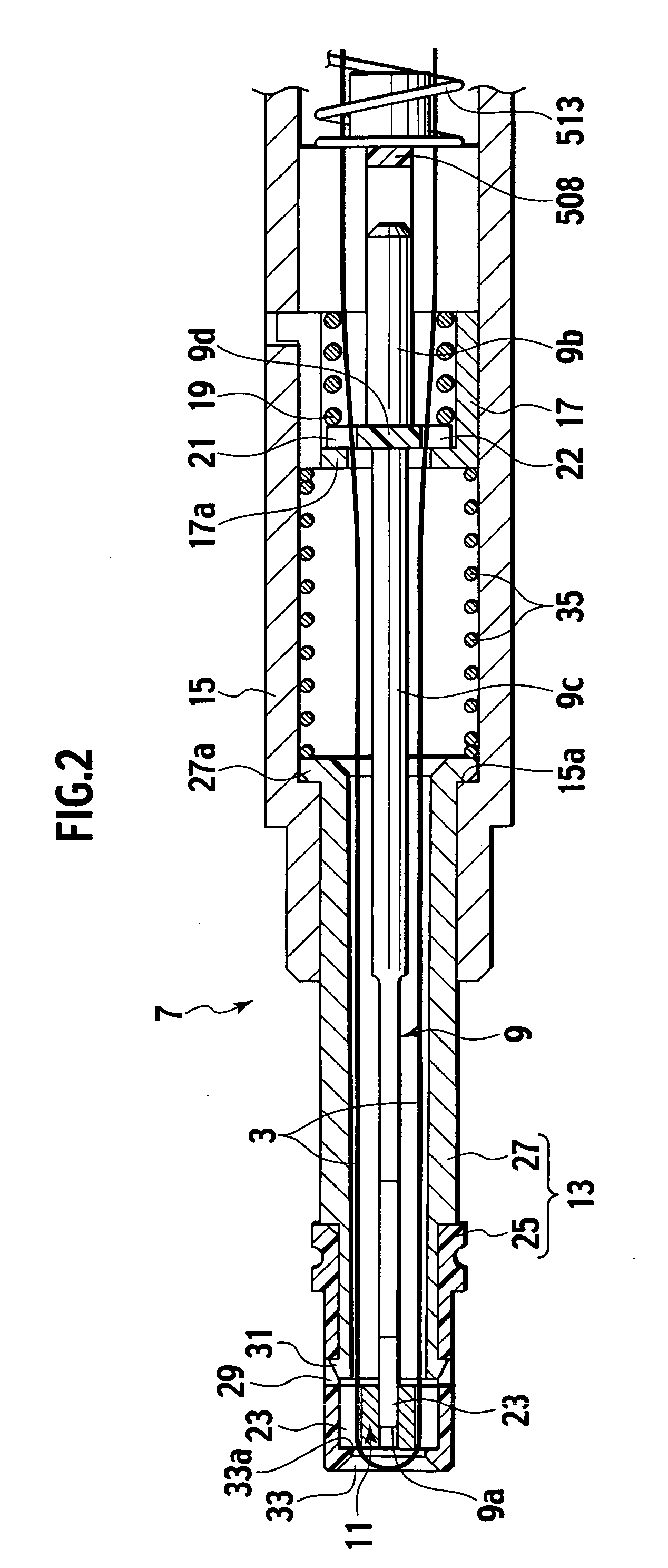
[0035] Referring to FIG. 2, the cleaning part 7 comprises an inner guide member 9 around which a cleaning tape 3 extends along the longitudinal direction thereof, a sliding member 11 slidably supported on the inner guide member 9, a tube shaped external guide member 13 that supports the sliding member 11 and encompasses the inner guide member 9 and the cleaning tape 3, and a tube shaped guide frame 15 that supports the external guide member 13.

[0036] The inner guide member 9 comprises a base part 9b and an extending part 9c that extends from the base part 9b toward the front (the left in FIG. 1).

[0037] This extendin...


PUM


Abstract

A cleaner for an optical fiber connector which is made up of an elongated inner guide member having a base and an end tip, around which a cleaning member extends along the extension axis thereof, from the base to the end tip and returning again to the base; a sliding member supported so as to be slidable along the inner guide member and having a pair of guide parts that guide the cleaning member, which can slide between a projected position protruding beyond the end tip of the inner guide member and a retracted position retreating beyond the end tip, such that when the sliding member is in the projected position, the cleaning member is positioned extending around the sliding member instead of around the end tip of the inner guide member; and a tubular shaped external guide member that supports the sliding member and encloses the inner guide member and the cleaning member.

Description

CROSS-REFERENCE TO RELATED APPLICATIONS [0001] This application claims benefit of priority to Japanese Patent Application No. 2005-10808, filed on Jan. 18, 2005, the entire contents of which are incorporated by reference herein. BACKGROUND OF THE INVENTION [0002] 1. Field of the Invention [0003] The present invention relates to a cleaner for an optical fiber connector used for cleaning a ferrule end face (connecting end face) of an optical fiber connector incorporated in optical communications equipment and the like. [0004] 2. Description of Related Art [0005] An optical fiber connector incorporated in equipment such as optical communications equipment and the like is connected and disconnected frequently. When such an optical fiber connector is disconnected dust or grease or the like may become attached to the end face of the ferrule of the optical fiber connector causing a deterioration in transmission performance. For this reason, the ferrule end face is cleaned when connecting o...

Claims


Application Information

Patent Timeline
Patent Type & Authority Applications(United States)
IPC IPC(8): B08B1/00
CPCB08B1/00B08B11/00B08B2240/02G02B6/3807G02B6/3866
Inventor KIDA, TAKAHISA
Owner SEIKOH GIKEN
Why Eureka
Try Eureka