Hand triggered tissue sealant spray apparatus and system

a technology of tissue sealant and spray apparatus, which is applied in the direction of instruments, combustion types, packaging foodstuffs, etc., can solve the problems of awkward timing of the supply and the ejection of tissue sealant or its components, and it is difficult for the user to coordinate the timing of these two separate motions

Active Publication Date: 2006-08-31
BAXTER INT INC +1
View PDF28 Cites 38 Cited by
  • Summary
  • Abstract
  • Description
  • Claims
  • Application Information

AI Technical Summary

Benefits of technology

[0022] This summary is not intended as an exhaustive identification of each aspect or feature of the present invention that is now or may hereafter be claimed, but represents a summary of certain aspects of the present invention to assist in understanding the more detailed description that follows. Additional aspects or features of the present invention may be set forth in the following description.
[0023] Although described later in terms of certain structures, it should be understood that the system and apparatuses of the present invention are not limited to the identical structures shown. It should be understood that the structures described and claimed are intended to have a broad interpretation that includes all of the more specific structures, such as those mentioned above, in which it may find commercial application.

Problems solved by technology

However, synchronizing the timing of this supply with the ejection of tissue sealant or its components has proven awkward and difficult, particularly where multiple tissue sealant components are used.
It has proven difficult for the user to coordinate the timing of these two separate motions.

Method used


Image

  • Hand triggered tissue sealant spray apparatus and system
  • Hand triggered tissue sealant spray apparatus and system
  • Hand triggered tissue sealant spray apparatus and system

Examples


Embodiment Construction

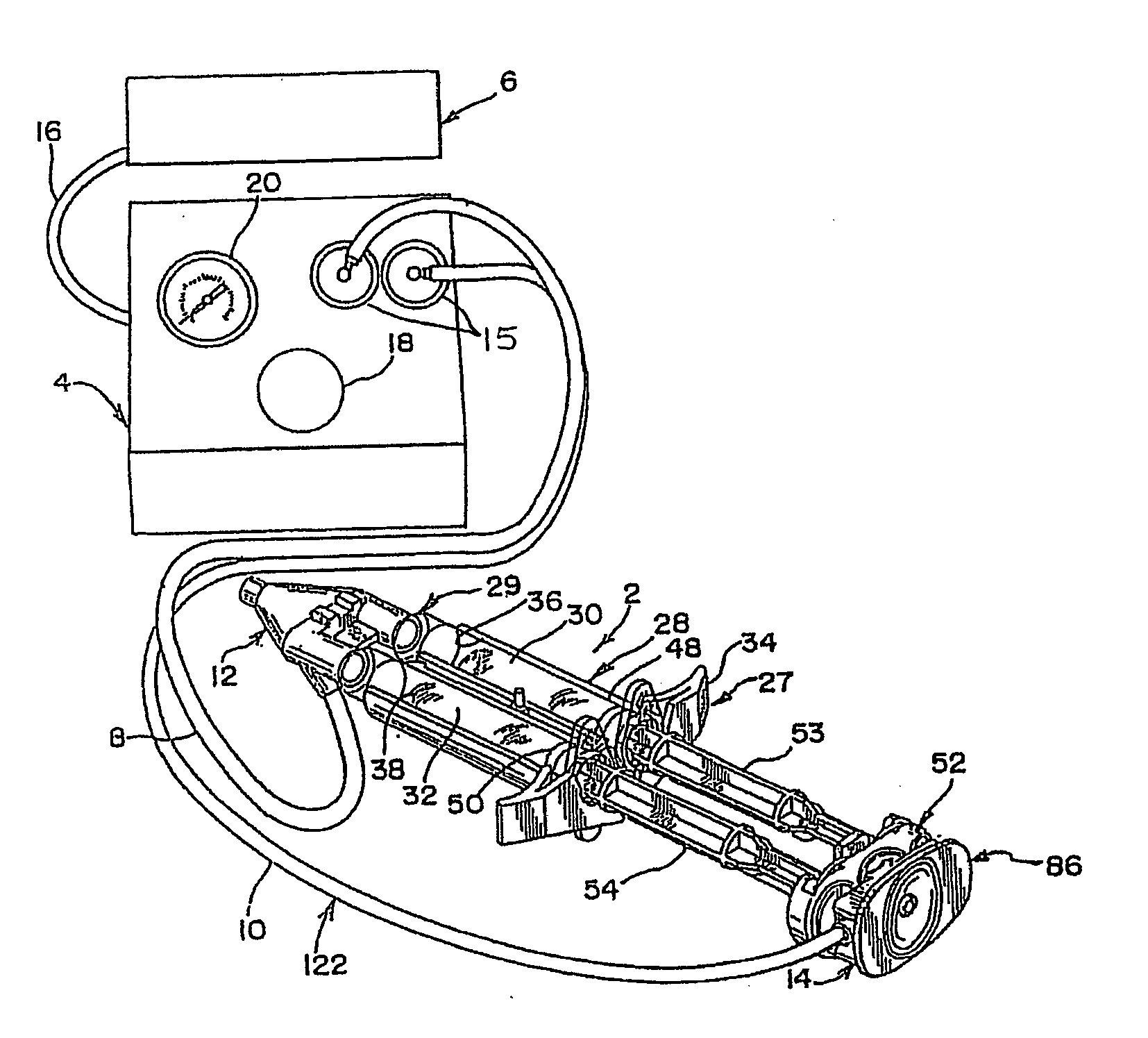
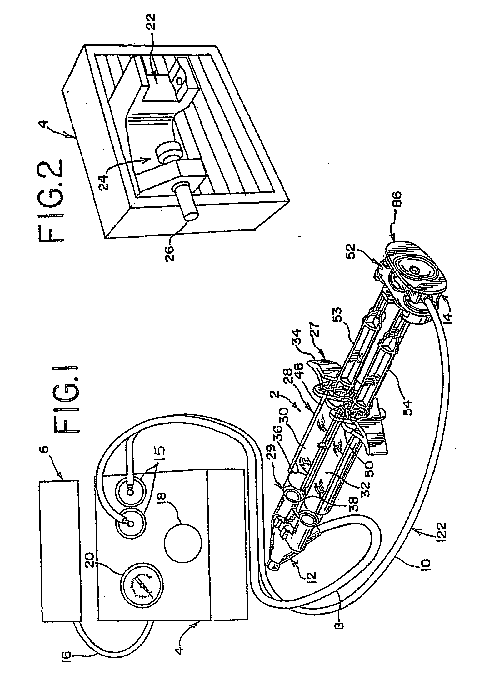
[0057] In accordance with one aspect of the present invention, FIG. 1 generally illustrates a system for applying sealant, such as tissue sealant, to a work surface, such as biological tissue. The system preferably includes a tissue sealant apparatus, generally indicated at 2, a control unit, generally indicated at 4, and a pressurized, sterile gas or air supply source, generally indicated at 6. Each of these structures will be described in further detail below in accordance with various aspects of the invention.

[0058] In FIG. 1, the tissue sealant apparatus 2 includes a distal end, generally indicated at 12, and a proximal end, generally indicated at 14. The apparatus 2 is preferably connected to the control unit 4 by first and second gas passageways 8 and 10, respectively, which may be formed, at least in part, by tubing which preferably connects the control unit 4 and the apparatus 2. Generally, the first gas passageway 8 is associated or fluidly communicates with the distal end...


PUM


Abstract

The present invention is generally directed to various structures for applying a sealant to a work surface. In one aspect of the invention, a sealant applicator assembly is provided for use with an apparatus of the type having an elongated body defining an interior bore and having a piston movably positioned in the bore and a pusher member operatively associated with the piston. The assembly comprises a spray adaptor adapted to communicate with the bore of the body and defining a distal outlet. A first gas passageway is cooperatively associated with the distal outlet and configured to direct gas to create a spray discharge of the sealant. An actuating member is adapted to be cooperative associated with a pusher member to eject sealant through the distal outlet and is operative to simultaneously actuate a supply of gas to the first gas passageway for creating a spray discharge of sealant.

Description

CROSS REFERENCE TO RELATED APPLICATION [0001] This application claims priority to U.S. Provisional Application Ser. No. 60 / 643,368, filed Jan. 12, 2005, which is incorporated by reference herein.BACKGROUND [0002] This invention relates to a system and apparatus for applying tissue sealant, such as tissue sealant, to a work surface, such as biological tissue. [0003] Mixing and / or applying sealant to work surfaces has application in a variety of settings. In the medical field, sealant in the form of tissue sealants have been applied to human and animal tissue, for example, to seal or repair tissue at a surgical or wound site, to stop bleeding, seal wounds, treat burns or skin grafts and a variety of other purposes. [0004] In the medical field, tissue sealant has typically been applied by a syringe-type applicator that ejects tissue sealant directly onto the tissue. Examples of such applicators are shown in U.S. Pat. Nos. 4,846,405, 5,582,596, 5,665,067, 6,461,361 and 6,585,696, and PC...

Claims


Application Information

Patent Timeline
Patent Type & Authority Applications(United States)
IPC IPC(8): G01F11/00B67D7/60B67D7/70
CPCA61B17/00491A61B2017/00495B05B7/0408B05C17/015B05C17/00516B05C17/00553B05C17/00566B05B7/0483A61J1/05
Inventor REDL, HEINZKHAKPOUR, ZAFARARIAGNO, SCOTT R.KELLNER, ANDREASZAKARIJA, LILLIAN G.
Owner BAXTER INT INC
Why Eureka
Try Eureka