
Heat dissipating fan assembly

Inactive Publication Date: 2006-08-31
HSIEH HSIN MAO
View PDF17 Cites 11 Cited by
  • Summary
  • Abstract
  • Description
  • Claims
  • Application Information

AI Technical Summary

Benefits of technology

[0006] The primary objective of the present invention is to provide a heat dissipating fan assembly to achieve low-noise operation.

Problems solved by technology

It is widely accepted that using a cooling fan in electronic appliances greatly helps maintain the operational efficiency of the electronic appliances because heat generated from the electronic appliances impedes their performance.
However, irritating noises are often generated by such fans due spinning of a rotor in a bearing.
That is, the conventional cooling fan includes either a ball bearing or a self-lubrication bearing and both of them have different problems.
When the bearing is used, the balls rotating inside the bearing casing will be gradually worn due to friction with the inner sidewall of the bearing casing.
This wear leads to noise during operation of the appliance.
The self-lubrication bearing does have lower noise than that of the ball bearing due to the addition of lubrication oil, but the lubrication oil loss during the operation over the time becomes the major drawback to this type of bearing.
That is, dryness of the bearing causes friction and corresponding noise.

Method used


Image

  • Heat dissipating fan assembly
  • Heat dissipating fan assembly
  • Heat dissipating fan assembly

Examples


Embodiment Construction

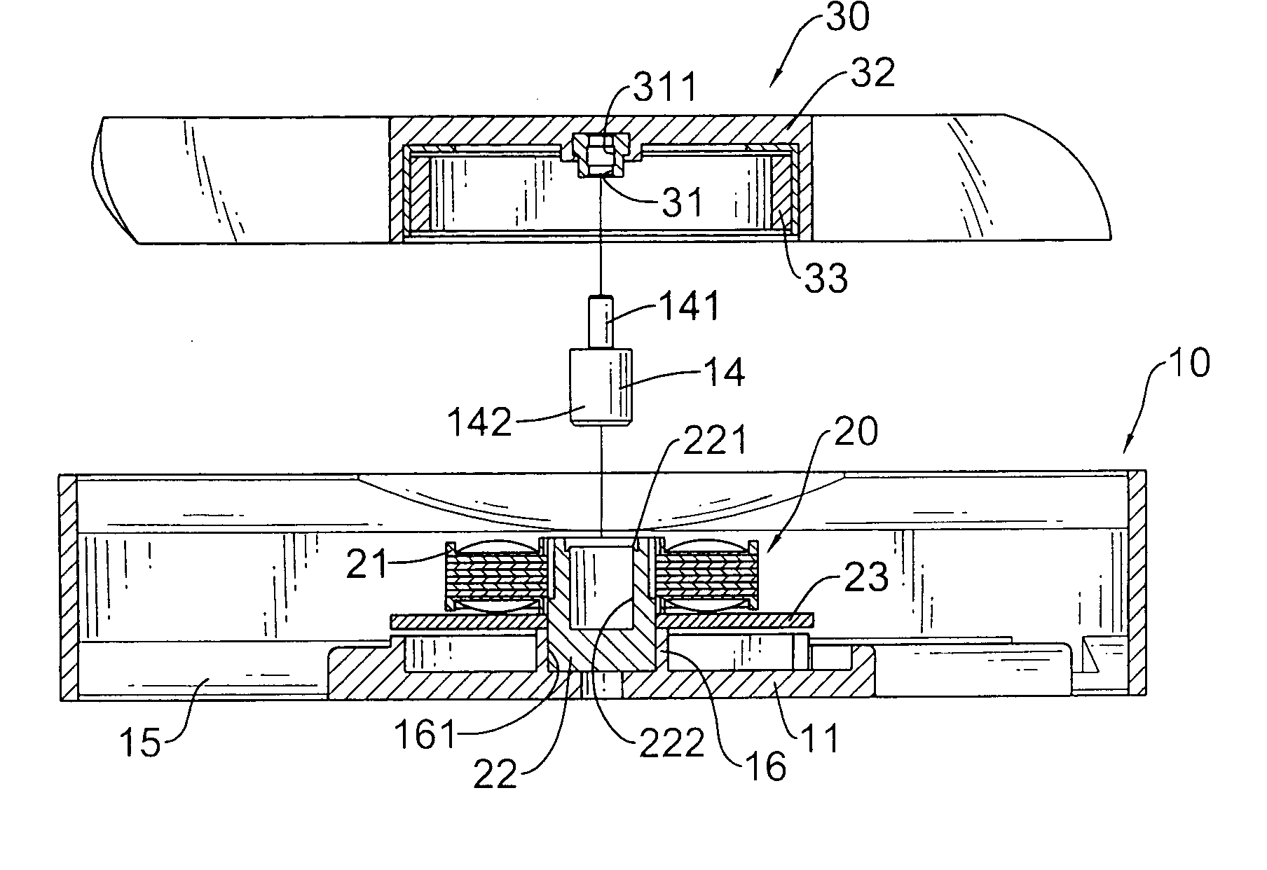
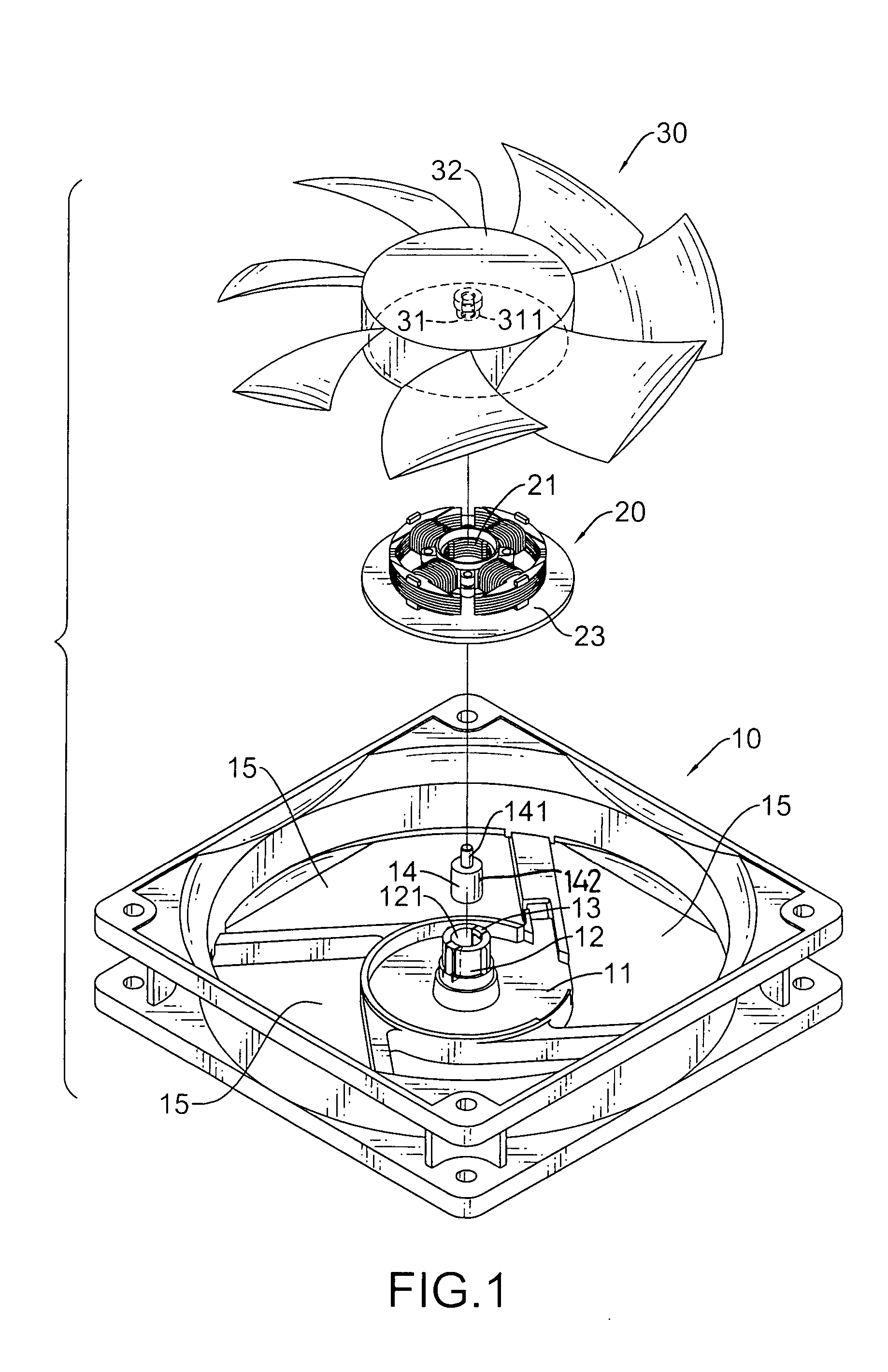
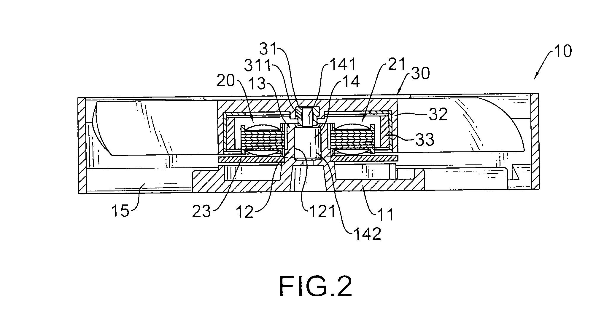
[0014] With reference to FIGS. 1 and 2, it is noted that the heat dissipating fan assembly in accordance with the present invention includes a frame (10), a stator (20) and a rotor (30).

[0015] The frame (10) is provided with a receiving space (not numbered) and a sleeve (12) is formed on a bottom face (11) of the receiving space. The sleeve (12) defines therein a connection hole (121) and has two opposed hooks (13) formed on a top periphery of the connection hole (121). Ventilation holes (15) are defined through the bottom face (11) of the frame (10) to communicate with the receiving space of the frame (10). Further, a bearing (fluid dynamic bearing; FDB) (14) is provided to the heat dissipating fan assembly of the present invention. The bearing (14) includes a hollow cylindrical portion (142) and a bearing shaft (141) extending out of the cylindrical portion (142) and rotatably received inside the cylindrical portion (142). Further, grease is provided between the cylindrical porti...


PUM


Abstract

A heat dissipating fan assembly includes a frame provided with multiple ventilation holes, a sleeve on top of a bottom face defining the receiving space and having a connection hole and two opposed retainers formed on a top peripheral edge of the sleeve, a bearing, a stator securely mounted around the sleeve and having a coil set mounted on a circuit board and a rotor having a hollow casing, multiple blades formed on an outer periphery of the hollow casing and a bearing shaft hole defined in a bottom face of the hollow casing to securely receive therein the bearing shaft, the bearing shaft hole having a mediate portion provided with a diameter larger than that of the bearing shaft such that extension of the bearing shaft into the bearing shaft hole reduces possibility of damage to the bearing shaft.

Description

BACKGROUND OF THE INVENTION [0001] 1. Field of the Invention [0002] The present invention relates to a heat dissipating fan assembly, and more particularly to a heat dissipating fan assembly having a rotor provided with an assembly hole which at a mediate portion thereof has an inner diameter larger than an outer diameter of a bearing shaft extending from a top face of a bearing such that due to the non-engagement relationship between the bearing and the rotor, rotational noise between the rotor and the bearing is low. [0003] 2. Description of Related Art [0004] It is widely accepted that using a cooling fan in electronic appliances greatly helps maintain the operational efficiency of the electronic appliances because heat generated from the electronic appliances impedes their performance. Accordingly, cooling fans have become standard equipment in the electronic appliances. However, irritating noises are often generated by such fans due spinning of a rotor in a bearing. That is, th...

Claims


Application Information

Patent Timeline
IPC IPC(8): H02K9/06
CPCF04D29/0563F04D29/057H02K5/1675
Inventor HSIEH, HSIN-MAO
Owner HSIEH HSIN MAO
Learn More