
Minaturized parallel coupled line filter using lumped capacitors and grounding and fabrication method thereof
- Summary
- Abstract
- Description
- Claims
- Application Information
AI Technical Summary
Benefits of technology
Problems solved by technology
Method used
Image

Examples
Embodiment Construction
[0062] Exemplary embodiments of the present invention will be described herein below with reference to the accompanying drawings.
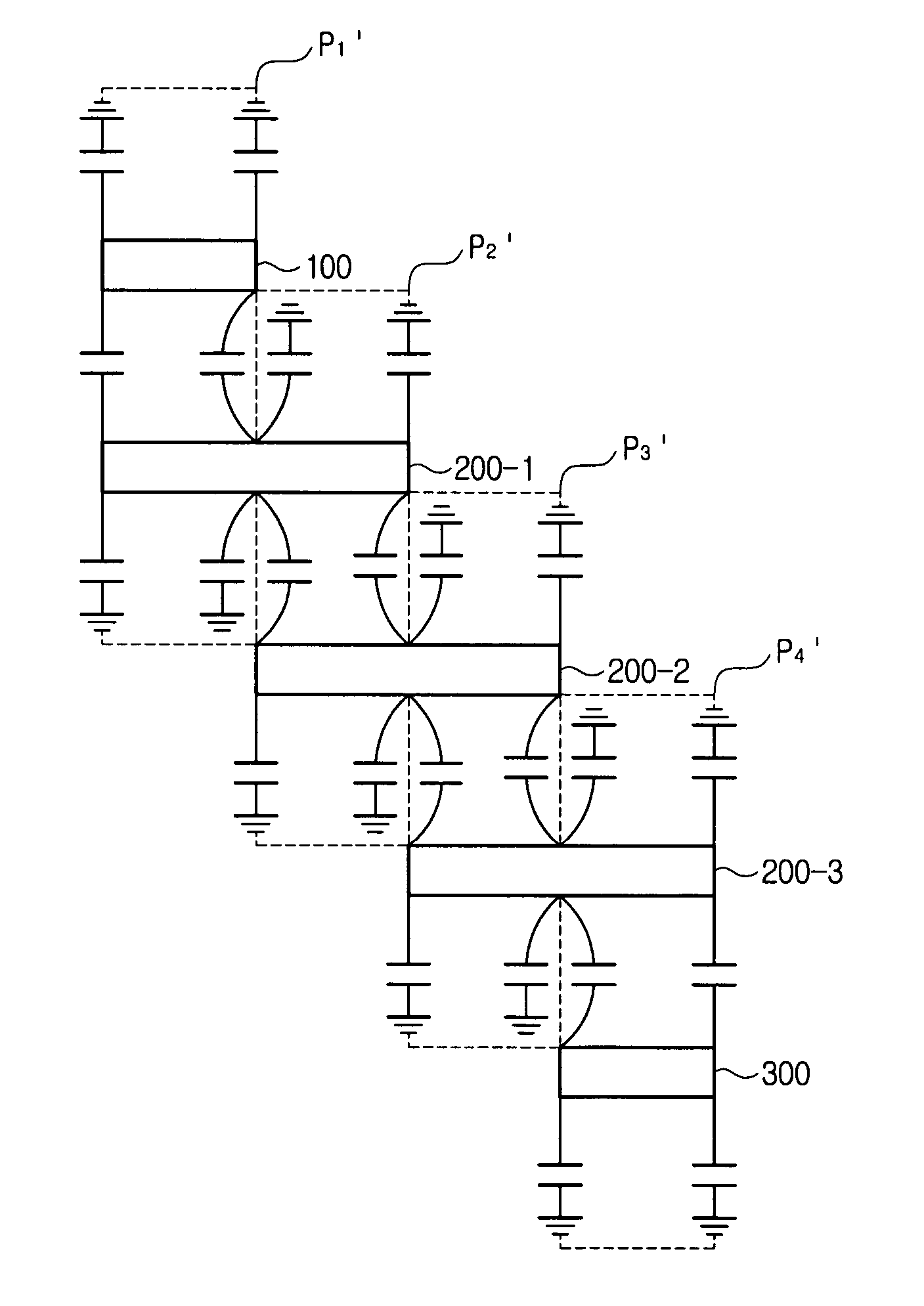
[0063]FIG. 4 illustrates a typical parallel coupled line filter. In particular, FIG. 4 shows a 3rd order parallel coupled line filter, which includes an input line 10, an output line 30, and three transmission lines 20-1, 20-2, 20-3 between the input line 10 and the output line 30.
[0064] An N-th order parallel coupled line filter is composed of (N+1) parallel coupled lines. For instance, the 3rd order parallel coupled line filter shown in FIG. 4 has four parallel coupled lines P1, P2, P3 and P4.
[0065] In FIG. 4, the assumed lengths of the transmission lines 20-1, 20-2, 20-3 are 180° (=λ / 2), respectively, and the assumed lengths of the input line 10 and the output line 30 are 90° (=λ / 4), respectively. Particularly, the parallel coupled line P2 of FIG. 4 is depicted in FIG. 5A.
[0066] The length θ of the parallel coupled line in FIG. 5A is 90° (=λ / 4). Als...
PUM
 Abstract
Description
Claims
Application Information